Semana 6
Esta semana vamos a realizar un recorrido rápido por el sistema operativo de tiempo real FreeRTOS. Vamos a introducir algunos conceptos generales y conceptos particulares.
Lecturas
En los siguientes sitios web se describe las características de la plataforma a utilizar (tanto hardware como software):
- Características generales de la plataforma ESP32.
- Guía de programación ESP-IDF.
- Tarjeta de desarrollo: ESP32-PICO-KIT V4 board.
Ejercicio 1: Configuración de las herramientas
Vamos a configurar el entorno de desarrollo como lo indica la guía de programación ESP-IDF. Específicamente, seguiremos los pasos indicados en la sección Get started. Antes de continuar con los pasos siguientes es fundamental que seamos capaces de configurar, compilar, programar y comunicarnos con la tarjeta. Todos los pasos anteriores desde la línea de comandos (bueno, tal vez la comunicación serial no). Para las comunicaciones serial podemos utilizar la terminal de arduino o programas como Hercules o CoolTerm.
En la documentación anterior sugieren utilizar eclipse como entorno integrado de desarrollo. Como sé que hay personas que no les gusta eclipse (alias Simón), también podemos utilizar Visual Studio Code (me está gustando más). El siguiente video en youtube muestra cómo configurar visual studio code. En la descripción del video está el enlace para descargar los archivos necesarios. Una tercera opción, la cual utilizaré tabién es visualGDB; sin embargo, esta herramienta no es gratis, es para gente de modo.
Hola mundo sin IDE
En esta sesión ilustraré los pasos necesarios para probar la instalación de las herramientas desde la línea de comandos. Estas pruebas son fundamentales antes de pensar en la instalación de un IDE.
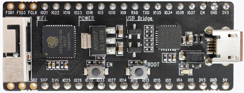
1. Lo primero que necesitamos para trabajar con la plataforma ESP32 es una serie de herramientas que permitan traducir código de lenguaje C a código de máquina de la plataforma objetivo (target). Todo este proceso lo haremos directamente en el computador (host) que puede tener un sistema operativo Linux, Windows o MacOS. El resultado de la traducción será un archivo binario que contendrá instrucciones en código de máquina del ESP32. Estas instrucciones tendremos que almacenarlas en la memoria no volátil del ESP32 (memoria flash). El proceso de almacenamiento se realiza con la ayuda de un bootloader. Un bootloader es un programa que se ejecutará en el ESP32 y tendrá por reposabilidades recibir la información del archivo binario y almancenarla en la memoria. Esta operación se realiza, en principio, mediante el puerto serial; sin embargo, podríamos hacer lo mismo utilizando otros medios tales como un interfaz ethernet, wifi, una memoria no volátile externa, entre otros. Pregunta Juanito: ¿Y cómo hacemos para ejercutar el bootloader? La respuesta larga está aquí. La respuesta corta: el pin GPIO0 debe estar en estado lógico bajo y mantenerse así mientras el ESP32 es reiniciado. Las siguiente figura muestra los push buttons de la tarjeta de desarrollo que permiten realizar la operación:
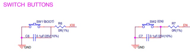
Afortunadamente, la secuencia anterior de acciones se puede automatizar desde la interfaz USB-Serial mediante el script esptool.py. Este script, que hace parte del toolchain, envía la información de la traducción y controla las líneas RTS y DTR que a su vez permiten controlar el pin GPIO0 y el pin de reset del ESP32. La siguiente figura muestra en detalle el esquemático de la interfaz USB-Serial:
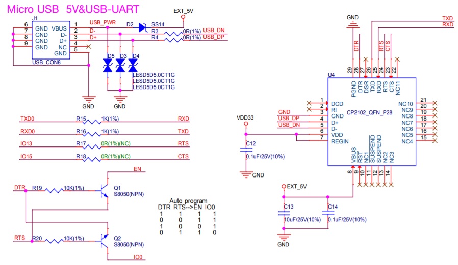
Volviendo de nuevo al asunto del toolchain, en la siguiente figura se observa el mismo concepto pero esta vez recordando lo estudiado en sensores 1 con la plataforma Arduino UNO.
En mi caso, la siguiente figura muestra una imagen del toolchain, para windows y precompilado por espressif, descomprimida:
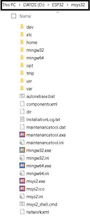
Esta estructura emula un entorno similar al que se enfrentaría un usuario de Linux o MacOS.
2. Ya habíamos dicho que en esta parte del proceso no utilizaremos un IDE. Por tanto, la herramienta para realizar todas
las operaciones será una terminal de línea de comandos, en mi caso: D:\ESP32\msys32\mingw32.exe. Antes de continuar con
la descarga del framwork de desarrollo, vamos a crear una carpeta para almacenarlo. Utilice los comandos de terminal
mkdir -p ~/esp32 para crear el directorio y cd ~/esp para cambiarse (navegar) de directorio.
3. Vamos a descargar el framework de desarrollo. Pregunta Juanito ¿Qué es un framework? Podemos entender un framework
como una aplicación incompleta, es decir, la empresa espressif nos entrega parte de nuestra aplicación hecha, pero nosotros
debemos completarla con la funcionalidad particular que deseamos. El framework se denomina ESP-IDF que
quiere decir Espressif IoT Development Framework. Para descargarlo debemos abrir la terminal y ejecutar los siguientes
comandos:
cd ~/esp
git clone --recursive https://github.com/espressif/esp-idf.git
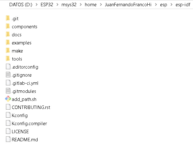
El ESP-IDF se descargará en la carpeta ~/esp/esp-idf. La siguiente figura muestra donde está dicha carpeta:
Note
El símbolo
~significa directorio raíz del usuario.Si por algún motivo olvidó utilizar la opción
--recursive, es necesario ejecutar los siguientes comandos para bajar el framework completo:cd ~/esp/esp-idf git submodule update --init
4. Ahora debemos configurar la ruta donde está ubicado el ESP-IDF. Para ello, debemos crear un script en la carpeta
D:\ESP32\msys32\etc\profile.d que nombraremos export_idf_path.sh. Escriba en el archivo:
export IDF_PATH="D:/ESP32/msys32/home/JuanFernandoFrancoHi/esp/esp-idf"
Salvamos el script y CERRAMOS la terminal. Al abrir de nuevo la terminal y ejecutar el comando:
printenv IDF_PATH
Debe aparecer la ruta previamente configurada. De lo contrario, será necesario verificar los pasos anteriores.
Creamos un projecto. Copiamos en el directorio
~/espuno de los ejemplos que vienen con el ESP-IDF así:cd ~/esp cp -r $IDF_PATH/examples/get-started/hello_world .
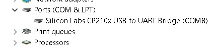
Conectamos el ESP32 al PC e identificamos el puerto serial asignado por el sistema operativo:
Vamos a configurar el ESP-IDF utilizando la herramienta
menuconfig:cd ~/esp/hello_world make menuconfig
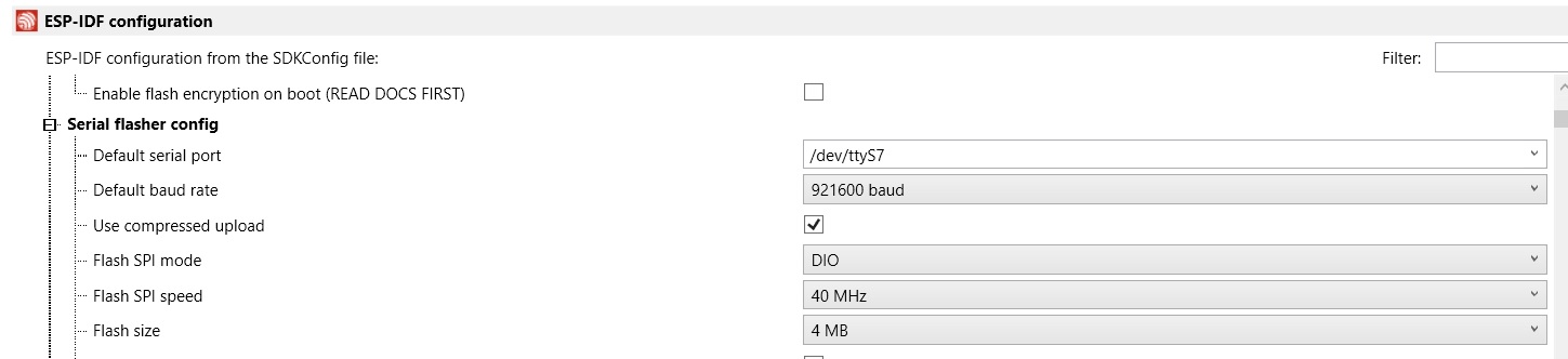
Debe aparecer la siguiente ventana:
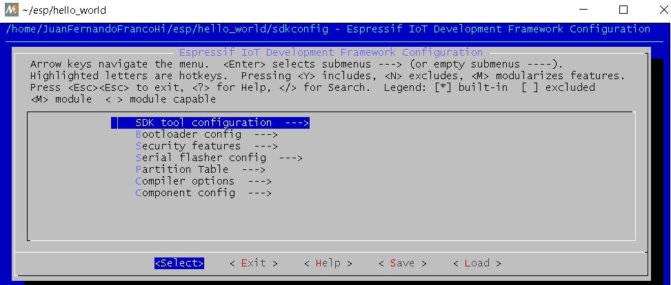
Navegar al menú Serial flasher config > Default serial port para configurar el puerto serial y la velocidad:
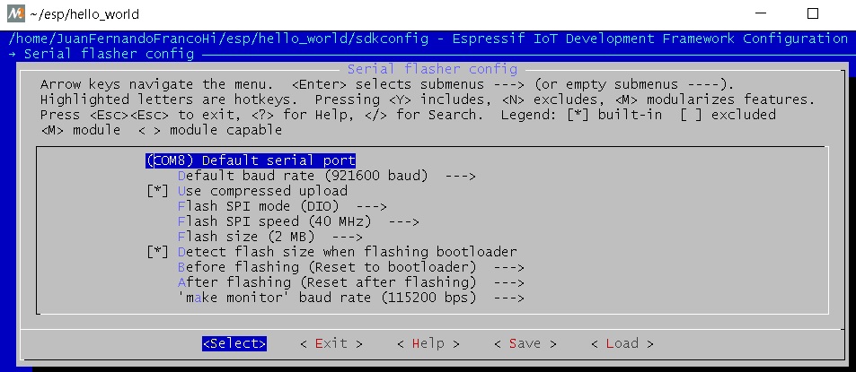
Confirmar las selecciones con enter. No olvide salvar seleccionando < Save > y luego salir seleccionando < Exit >.
Compilar y almacenar el programa en la memoria flash. En la terminal escribimos el comando:
make flash
Este comando hace varias cosas: compilar la aplicación y todos los componentes del ESP-IDF, genera el bootloader, la tabla de particiones, los binarios de la aplicación y finalmente envía el binario al ESP32.
- Una vez almacenado el binario de la aplicación en la memoria flash, podemos abrir una terminal serial a 115200 para observar el resultado.
10. Pregunta Juanito ¿Y esto toca hacerlo cada que creemos una aplicación? La respuesta es si y no. No es necesario bajar el ESP-IDF y configurarlo; sin embargo, si es recomendable seguir estos pasos:
- Copiar un proyecto existente.
- Configurar el framework:
make menuconfig. - Compilar el proyecto:
make all. Esto compila la aplicación, el bootloader y la tabla de partición. - Grabar todo el proyecto:
make flash. - Luego, compilar sólo la aplicación:
make app. Esto acelara el proceso al evitar compilarlo todo. - Luego, grabar sólo la aplicación:
make app-flash.
11. Pregunta Juanito ¿Y si Espressif actualiza el toolchain? Cambio el nombre del directorio de
D:\ESP32\msys32 a D:\ESP32\msys32\mingw32_old y repito todo el procedimiento desde la descarga del toolchain
12. Pregunta Juanito ¿Y si Espressif no actualiza el toolchain pero si actualiza el ESP-IDF? cambio el direcorio ~/esp/esp-idf por ~/esp/esp-idf_old y clono de nuevo el ESP-IDF:
cd ~/esp
git clone --recursive https://github.com/espressif/esp-idf.git
Configuración de Visual Studio Code (VSC)
A continuación describiré los pasos necesarios para configurar la herramienta. Esta sección supone que los pasos anteriores se siguieron y el resultado fué exitoso. Esto es importante porque la función de VSC es llamar automáticamente los mismos comandos que estamos llamando manualmente.
- Lo primero que debemos hacer es descargar visual studio code.
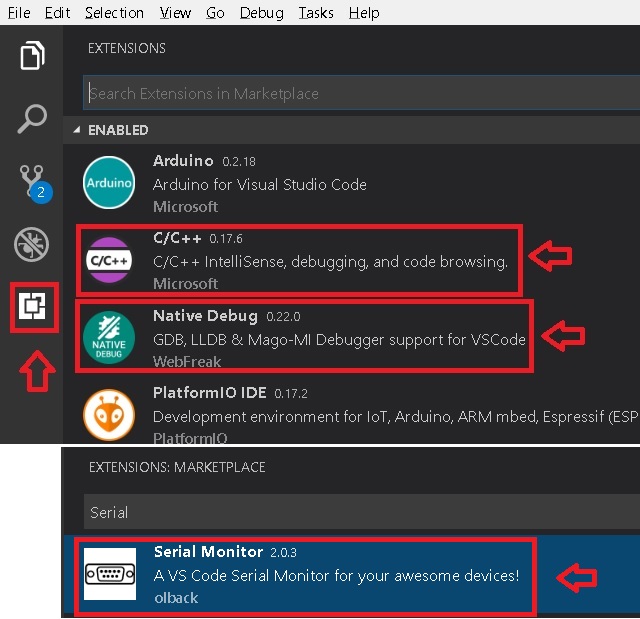
2. Luego se deben instalar algunas extensiones: C/C++ for Visual Studio Code, Native Debug (para el futuro, pero nosotros no utilizaremos el debugger porque no tenemos una interfaz JTAG), Serial Monitor como muestra la siguiente figura:
3. Ahora configuramos la terminal desde la que VSC llamará los comandos. Seleccionar File -> Preferences -> Settings y adicionar el siguiente texto a las
preferencias actuales:
"terminal.integrated.shell.windows": "D:/ESP32/msys32/usr/bin/bash.exe",
"terminal.integrated.shellArgs.windows": [
    "--login",
],
"terminal.integrated.env.windows": {
    "CHERE_INVOKING": "1",
    "MSYSTEM": "MINGW32",
}
Es de notar la ruta de la aplicación bash.exe en mi sistema: D:/ESP32/msys32/usr/bin/bash.exe. En mi caso, los Settings quedan así:
{
    "terminal.integrated.shell.windows": "D:/ESP32/msys32/usr/bin/bash.exe",
    "terminal.integrated.shellArgs.windows": [
        "--login",
    ],
    "terminal.integrated.env.windows": {
        "CHERE_INVOKING": "1",
        "MSYSTEM": "MINGW32",
    },
    "arduino.path": "C:/Users/JuanFernandoFrancoHi/arduino-1.8.5-windows/arduino-1.8.5",
    "arduino.logLevel": "info", "arduino.enableUSBDetection": true,
    "C_Cpp.intelliSenseEngine": "Tag Parser",
    "files.autoSave": "afterDelay",
    "python.pythonPath": "C:\\Users\\JuanFernandoFrancoHi\\AppData\\Local\\Programs\\Python\\Python36-32\\python.exe",
    "arduino.additionalUrls": [
        "https://git.oschina.net/dfrobot/FireBeetle-ESP32/raw/master/package_esp32_index.json",
        "http://arduino.esp8266.com/stable/package_esp8266com_index.json",
        "https://github.com/stm32duino/BoardManagerFiles/raw/master/STM32/package_stm_index.json",
        "https://raw.githubusercontent.com/VSChina/azureiotdevkit_tools/master/package_azureboard_index.json"
    ]
}
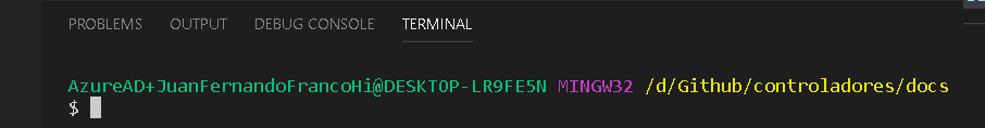
4. Verificamos que la terminal esté correctamente configurada. Seleccionamos el menú View --> Output y finalmente clock en Terminal. El resutado debe ser
similar al que muestra la figura:
Iniciar un nuevo proyecto en Visual Studio Code
Copiamos de la carpeta de ejemplos del ESP-IDF el proyecto hello_world:
cd ~/esp
mkdir vscode-workspace
cd vscode-workspace
cp -r $IDF_PATH/examples/get-started/hello_world .
2. Copiamos la carpeta .vscode en el directorio hello_world. Esta carpeta tiene dos
archivos: c_cpp_properties.json y tasks.json. El archivo c_cpp_properties.json tiene el path de los include del proyecto, del ESP-IDF, del
toolchain, entre otros.
Note
No olvide ajustar los path con la ruta adecuada en su sistema.
Tenga en cuenta que este archivo lo podrá seguir reutilizando con cada proyecto que cree.
El archivo tasks.json tiene configuradas las tareas para compilar, programar, entre otras. En este caso vamos a editar las siguiente tareas:
flash appybuild app: cambiamos uno de losargspor -jX donde X será el número de cores disponibles en su computador. En mi caso, X será 4.monitorymenuconfig: cambiar el path decommandpara ajustarlo a su sistema. En mi caso"D:/ESP32/msys32/mingw32.exe"
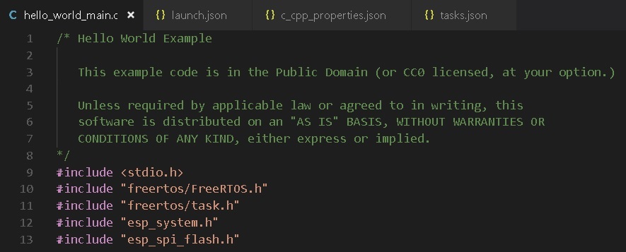
3. Abrimos la carpeta hello_world en VSC: File -> Open Folder. Luego buscamos en el explorer de VSC el archivo hello_world_main.c. Si VSC reconoce
los includes no deben aparecer líneas verdes bajo las líneas #include como muestra la figura:
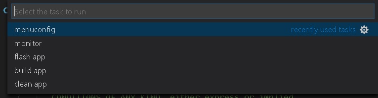
- Estamos listos para probar las tareas. Seleccione el menú
Tasks -> Run Taskso la tecla F12. Deben aparecer las tareas como se ve en la figura:
- Seleccionamos
clean apppara borrar compilaciones previas (si es que tenemos). - Seleccionamos
menuconfigpara configurar el framework a nuestro gusto. No olvide esperar la generación del archivo de configuración. - Seleccionamos
build apppara compilar la aplicación. - Seleccionamos
flash apppara almacenar el programa en la memoria flash. - Abrimos una terminal serial para verificar que efectivamente quedó programada la aplicación.
- Como ejercicio corto se recomienda realizar una pequeña modificación al código y repetir los pasos anteriores desde
build app.
Note
Debe notar que al realizar modificaciones al código, la velocidad de compilación aumenta considerablemente porque ya no es necesario compilar todo el framework.
Ejercicio 2: análisis del ejemplo
En este ejercicio vamos a analizar un poco el código del Ejercicio 1.
9 10 11 12 13 14 15 16 17 18 19 20 21 22 23 24 25 26 27 28 29 30 31 32 33 34 35 36 37 38 39 40 | #include <stdio.h>
#include "freertos/FreeRTOS.h"
#include "freertos/task.h"
#include "esp_system.h"
#include "esp_spi_flash.h"
void app_main()
{
printf("Hola sensores 2!\n");
/* Print chip information */
esp_chip_info_t chip_info;
esp_chip_info(&chip_info);
printf("This is ESP32 chip with %d CPU cores, WiFi%s%s, ",
chip_info.cores,
(chip_info.features & CHIP_FEATURE_BT) ? "/BT" : "",
(chip_info.features & CHIP_FEATURE_BLE) ? "/BLE" : "");
printf("silicon revision %d, ", chip_info.revision);
printf("%dMB %s flash\n", spi_flash_get_chip_size() / (1024 * 1024),
(chip_info.features & CHIP_FEATURE_EMB_FLASH) ? "embedded" : "external");
for (int i = 10; i >= 0; i--) {
printf("Restarting in %d seconds...\n", i);
vTaskDelay(1000 / portTICK_PERIOD_MS);
}
printf("Restarting now.\n");
fflush(stdout);
esp_restart();
}
|
Varios puntos a considerar:
Lo primero que debemos notar es el punto de entrada del programa, la función app_main(), línea 16. Al igual que el framework de arduino,
el punto de entrada de la aplicación es diferente a la función main(). Esto ocurre porque la función main()
hace parte del código del framework y ese éste quien llamará el código de la aplicación del usuario.
En la línea 18 se observa la función printf de la biblioteca #include <stdio.h>. Esta biblioteca permite enviar mensajes a la terminal serial a través
de la UART0 del ESP32.
En la línea 21 se observa la definición de una estructura de datos de tipo esp_chip_info_t. El lenguaje C no soporta de manera nativa objetos, por tanto,
es necesario crear estructuras de datos en memoria (simuladondo objetos) e inicializarlas empleando funciones, esp_chip_info(&chip_info);, a las cuales
se pasan las estructuras de datos por REFERENCIAS: &chip_info. En este caso el operador & obtiene la dirección de la variable chip_info. El
siguiente código muestra la definición de la estructura de datos esp_chip_info_t. Es de notar que la estructura de datos anida otra estructura de datos
esp_chip_model_t:
1 2 3 4 5 6 7 8 9 | /**
* @brief The structure represents information about the chip
*/
typedef struct {
esp_chip_model_t model; //!< chip model, one of esp_chip_model_t
uint32_t features; //!< bit mask of CHIP_FEATURE_x feature flags
uint8_t cores; //!< number of CPU cores
uint8_t revision; //!< chip revision number
} esp_chip_info_t;
|
Este código muestra la implementación de la función esp_chip_info:
1 2 3 4 5 6 7 8 9 10 11 12 13 14 15 16 17 18 19 20 21 22 23 24 25 26 27 28 29 30 31 | static void get_chip_info_esp32(esp_chip_info_t* out_info)
{
out_info->model = CHIP_ESP32;
uint32_t reg = REG_READ(EFUSE_BLK0_RDATA3_REG);
memset(out_info, 0, sizeof(*out_info));
if ((reg & EFUSE_RD_CHIP_VER_REV1_M) != 0) {
out_info->revision = 1;
}
if ((reg & EFUSE_RD_CHIP_VER_DIS_APP_CPU_M) == 0) {
out_info->cores = 2;
} else {
out_info->cores = 1;
}
out_info->features = CHIP_FEATURE_WIFI_BGN;
if ((reg & EFUSE_RD_CHIP_VER_DIS_BT_M) == 0) {
out_info->features |= CHIP_FEATURE_BT | CHIP_FEATURE_BLE;
}
int package = (reg & EFUSE_RD_CHIP_VER_PKG_M) >> EFUSE_RD_CHIP_VER_PKG_S;
if (package == EFUSE_RD_CHIP_VER_PKG_ESP32D2WDQ5 ||
package == EFUSE_RD_CHIP_VER_PKG_ESP32PICOD2 ||
package == EFUSE_RD_CHIP_VER_PKG_ESP32PICOD4) {
out_info->features |= CHIP_FEATURE_EMB_FLASH;
}
}
void esp_chip_info(esp_chip_info_t* out_info)
{
// Only ESP32 is supported now, in the future call one of the
// chip-specific functions based on sdkconfig choice
return get_chip_info_esp32(out_info);
}
|
La variable out_info es un puntero, es decir, una variable que almancena direcciones de otras variables y puede estar implementada
en los registros del procesador o en el stack (Pregunta Juanito: ¿Qué?). En este caso out_info, almacena la dirección de una variable de
tipo esp_chip_info_t. Note que luego el contenido de out_info se pasa otra variable out_info diferente a la primera. Esto ocurre al llamar
la función get_chip_info_esp32(out_info); (Pregunta Juanito: no charlemos tan pesado, ¿Cómo así?). No pierda de vista que
la dirección que estamos pasando de aquí para allá no es más que la dirección de chip_info. Finalmente, observe cómo se acceden las posiciones
de memoria de la variable chip_info mediante el puntero out_info, por ejemplo, out_info->features modifica la posición features de chip_info
mediante el operador -> (Pregunta el profe a Juanito: ¿Eres feliz?).
En la línea 23 se observan varias cosas interesante:
Primero, el uso de cadenas formateadas: "This is ESP32 chip with %d CPU cores, WiFi%s%s, ". El resultado de printf es:
This is ESP32 chip with 2 CPU cores, WiFi/BT/BLE,. Note que %d, %s%s no aparecen. En vez de eso, aparece el número 2 en vez de %d y la cadena /BT/BLE
en vez de %s%s. Lo que ocurre es que printf es capaz de detectar algunos caracteres especiales y cambiarlos por el resultado de evaluar
chip_info.cores, (chip_info.features & CHIP_FEATURE_BT) ? "/BT" : "" y (chip_info.features & CHIP_FEATURE_BLE) ? "/BLE" : "").
Estas dos últimas expresiones son condicionales que evaluan la condición de la izquierda del signo ?. Si la condición es verdadera, la expresión
devuelve el resultado de la expresión a la izquierda del signo :, de lo contrario, devuelve lo que esté a la derecha.
En la línea 35 se observa la función vTaskDelay(1000 / portTICK_PERIOD_MS);. Esta función es un llamado al sistema operativo, FreeRTOS, para
solicitar generar un retardo de 1 segundo. Para medir los tiempos, `FreeRTOS genera una base de tiempo o una interrupción periódica llamada tick del
sistema. La operación 1000 / portTICK_PERIOD_MS calcula la cantidad de ticks que hay en 1000 mili segundos. De esta manera le informamos al sistema
operativo cuántos ticks tardará el retardo.
La línea 38 muestra la función fflush(stdout);. Esta función bloquea el programa hastas que todos los caracteres pendientes por transmitir sean enviados
a través de la UART0. Pregunta Juanito: ¿Pero entonces qué hace printf? ¿No se supone que transmite una información por la UART0? En realidad, tal como
ocurre con el framework de arduino, la función printf realmente copia la información a un buffer de transmisión. Como el ESP32 corre tan rápido,
no es posible garantizar que al llegar al código de máquina correspondiente al la línea 38 toda la información se haya transmitido. En consecuencia, la función
fflush(stdout); hará que el ESP32 espere hasta que último dato se haya enviado.
En la línea 39, la función esp_restart permite reiniciar el ESP32 por software, es decir, no es necesario una acción por hardware para obligar al ESP32
a ejecutar de nuevo el programa almacenado.
Ejercicio 3: Entorno profesional de desarrollo
En el ejercicio 1 hablé de la herramienta visualGDB. Esta herramienta es muy práctica y útil, aunque no es gratis. Para utilizarla se recomienda descargar Visual Studio Enterprice, que es gratuita para la comunidad Unviersitaria de la escuela de Ingeniería, a través de la plataforma Microsoft Imagine ingresando con el correo y clave institucional.
Luego descargar e instalar VisualGDB 5.4 Preview 3.
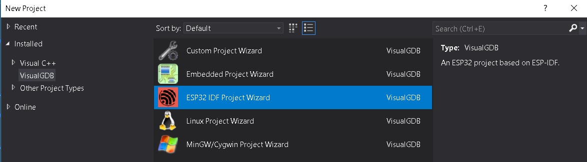
Crear un projecto seleccionado la opción que muestra la figura:
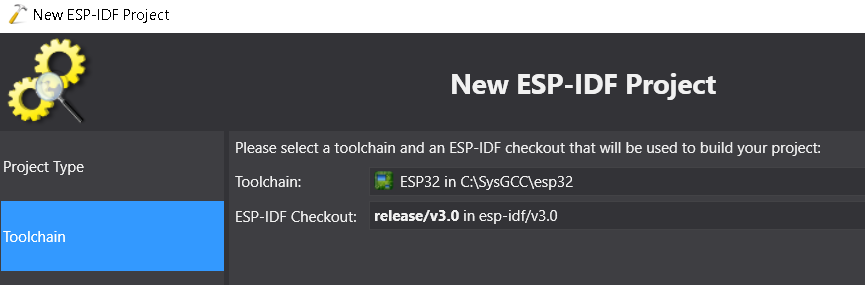
visualGDB utiliza su propio toolchain precompilado que debe ser descargado al momento de crear el proyecto. Una vez descargado, se selecciona como muestra la figura:
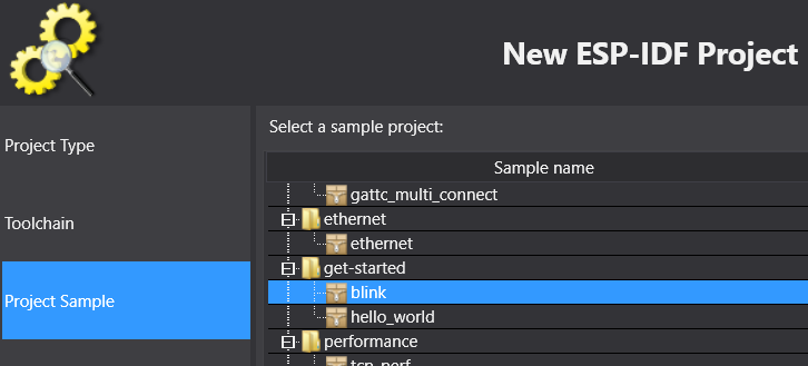
Seleccionar como Project Sample el proyecto blink:
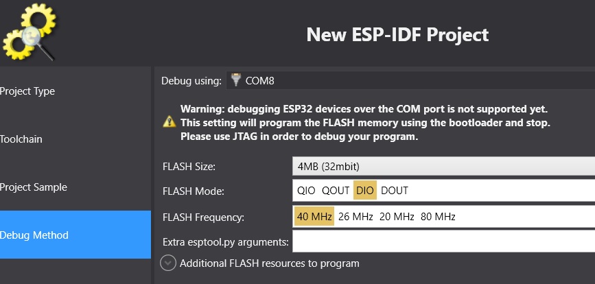
Finalmente seleccionar el Debug Method:
Al llegar a este punto estamos listos para desarrollar. Pregunta Juanito: ¿Y el tutorial para configurar la herramienta? No hay tutorial, la herramienta ya está lista para ser utilizada. Entonces procedemos así:
- Click derecho en el nombre del proyecto (ver el cuadro Solution Explorer). Seleccionar VisualGDB Project Properties.
- Configurar el ESP-IDF. Esto no es más que una versión más sencilla de menuconfig.
- Seleccionar ESP-IDF Project y configurar como muestra la figura, no olvidar dar clock en Apply y OK para salvar los cambios.
- Para compilar el programa seleccionar:
Build->Build Solution. - Para almacenar el programa en la memoria:
Debug->Start Without Debugging.
A continuación se muestra el código fuente de la aplicación:
9 10 11 12 13 14 15 16 17 18 19 20 21 22 23 24 25 26 27 28 29 30 31 32 33 34 35 36 37 38 39 40 41 42 43 44 | #include <stdio.h>
#include "freertos/FreeRTOS.h"
#include "freertos/task.h"
#include "driver/gpio.h"
#include "sdkconfig.h"
/* Can run 'make menuconfig' to choose the GPIO to blink,
or you can edit the following line and set a number here.
*/
#define BLINK_GPIO CONFIG_BLINK_GPIO
void blink_task(void *pvParameter)
{
/* Configure the IOMUX register for pad BLINK_GPIO (some pads are
muxed to GPIO on reset already, but some default to other
functions and need to be switched to GPIO. Consult the
Technical Reference for a list of pads and their default
functions.)
*/
gpio_pad_select_gpio(BLINK_GPIO);
/* Set the GPIO as a push/pull output */
gpio_set_direction(BLINK_GPIO, GPIO_MODE_OUTPUT);
while(1) {
/* Blink off (output low) */
gpio_set_level(BLINK_GPIO, 0);
vTaskDelay(1000 / portTICK_PERIOD_MS);
/* Blink on (output high) */
gpio_set_level(BLINK_GPIO, 1);
vTaskDelay(1000 / portTICK_PERIOD_MS);
}
}
void app_main()
{
xTaskCreate(&blink_task, "blink_task", configMINIMAL_STACK_SIZE, NULL, 5, NULL);
}
|
Ejercicio: analizar el código.
Ahora vamomos a explorar conceptos avanzados de programación de sistemas embebidos. En particular, mediante el uso de sistemas operativos de tiempo real (RTOS); sin embargo, antes de comenzar a utilizar las abstracciones que un RTOS nos ofrece, debemos comprender cómo funciona.
Algo de teoría
Los RTOS son una evolución de la arquitectura de programación clásica backgroud/foreground tan conocida por
nosotros (si, arduino). La idea entonces de un RTOS es ofrecernos un ambiente de programación con múltiples background
funcionando de manera concurrente, es decir, es como tener un programa de arduino con múltiples ciclos loop()
concurrentes.
El siguiente código muestra un ejemplo típico de una arquitectura background/foreground:
1 2 3 4 5 6 7 8 9 10 11 12 13 14 15 | // background code:
#include <stdint.h>
#include "bsp.h"
int main() {
BSP_init();
while (1) {
BSP_ledGreenOn();
BSP_delay(BSP_TICKS_PER_SEC / 4U);
BSP_ledGreenOff();
BSP_delay(BSP_TICKS_PER_SEC * 3U / 4U);
}
return 0;
}
|
1 2 3 4 5 6 7 8 9 10 11 12 13 14 15 16 17 18 19 20 21 22 23 24 25 26 27 28 29 30 31 32 33 34 35 36 37 38 39 40 41 42 43 44 45 46 | // foreground code: blocking version
#include <stdint.h> /* Standard integers. WG14/N843 C99 Standard */
#include "bsp.h"
#include "TM4C123GH6PM.h" /* the TM4C MCU Peripheral Access Layer (TI) */
/* on-board LEDs */
#define LED_BLUE (1U << 2)
static uint32_t volatile l_tickCtr;
void SysTick_Handler(void) {
++l_tickCtr;
}
void BSP_init(void) {
SYSCTL->RCGCGPIO |= (1U << 5); /* enable Run mode for GPIOF */
SYSCTL->GPIOHBCTL |= (1U << 5); /* enable AHB for GPIOF */
GPIOF_AHB->DIR |= (LED_RED | LED_BLUE | LED_GREEN);
GPIOF_AHB->DEN |= (LED_RED | LED_BLUE | LED_GREEN);
SystemCoreClockUpdate();
SysTick_Config(SystemCoreClock / BSP_TICKS_PER_SEC);
__enable_irq();
}
uint32_t BSP_tickCtr(void) {
uint32_t tickCtr;
__disable_irq();
tickCtr = l_tickCtr;
__enable_irq();
return tickCtr;
}
void BSP_delay(uint32_t ticks) {
uint32_t start = BSP_tickCtr();
while ((BSP_tickCtr() - start) < ticks) {
}
}
void BSP_ledGreenOn(void) {
GPIOF_AHB->DATA_Bits[LED_GREEN] = LED_GREEN;
}
void BSP_ledGreenOff(void) {
GPIOF_AHB->DATA_Bits[LED_GREEN] = 0U;
}
|
Es importante notar que el código anterior es bloqueante (Pregunta Juanito: ¿Qué es eso?). La función
BSP_delay(BSP_TICKS_PER_SEC / 4U); consume todos los recursos de la CPU en espera ocupada. A esto también lo llamamos
polling.
¿Cómo superamos la espera ocupada? Utilizando la excelente técnica de programación conocida como máquinas de estado:
1 2 3 4 5 6 7 8 9 10 11 12 13 14 15 16 17 18 19 20 21 22 23 24 25 26 27 28 29 30 31 32 33 34 35 36 37 | // background code: non-blocking version
int main() {
BSP_init();
while (1) {
/* Blinky polling state machine */
static enum {
INITIAL,
OFF_STATE,
ON_STATE
} state = INITIAL;
static uint32_t start;
switch (state) {
case INITIAL:
start = BSP_tickCtr();
state = OFF_STATE; /* initial transition */
break;
case OFF_STATE:
if ((BSP_tickCtr() - start) > BSP_TICKS_PER_SEC * 3U / 4U) {
BSP_ledGreenOn();
start = BSP_tickCtr();
state = ON_STATE; /* state transition */
}
break;
case ON_STATE:
if ((BSP_tickCtr() - start) > BSP_TICKS_PER_SEC / 4U) {
BSP_ledGreenOff();
start = BSP_tickCtr();
state = OFF_STATE; /* state transition */
}
break;
default:
//error();
break;
}
}
//return 0;
}
|
En ambos códigos, espera ocupada y máquinas de estado, la arquitectura background/foreground se puede entender como ilustra la figura:
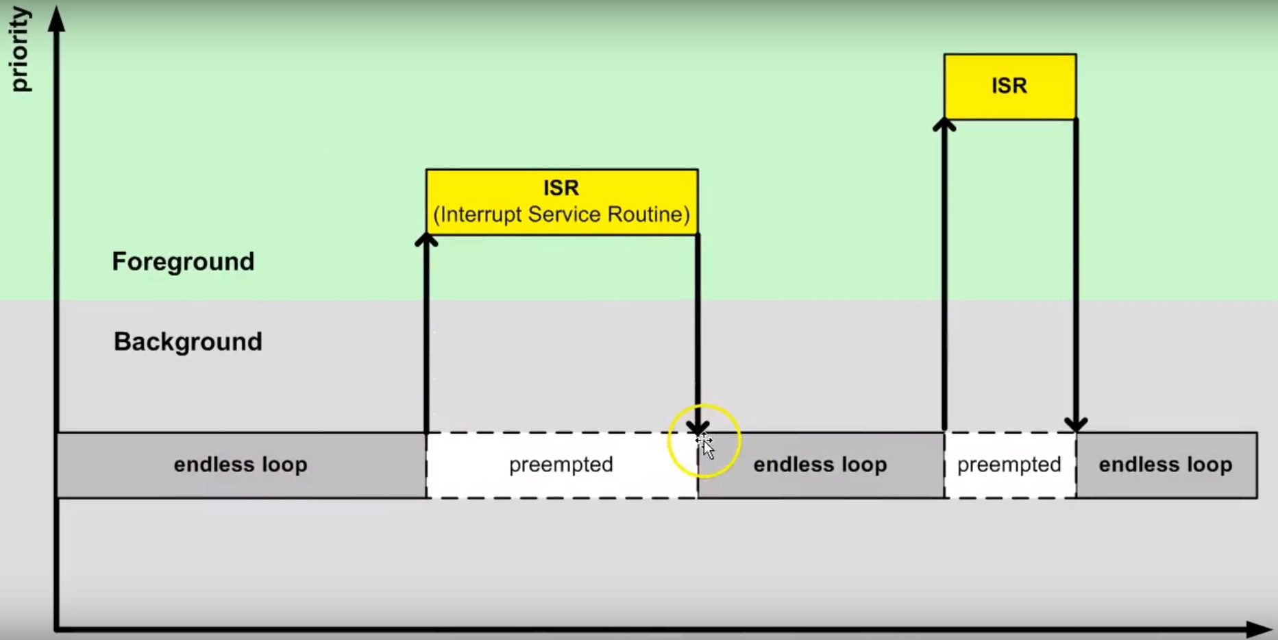
El código que enciende y apaga el LED corre en el background. Cuando ocurre la interrupción SysTick_Handler el
background será “despojado” de la CPU de la cual se apropiará (preemption) el servicio de atención a
la interrupción o ISR en el foreground. Una vez termine la ejecución de la ISR, el backgound retomará justo en el
punto en el cual fue “desalojado” (preempted). Note también que la comunicación entre el background/foreground se realiza
por medio de la variable l_tickCtr. Adicionalmente, observe como la función BSP_tickCtr accede la variable.
Pregunta Juanito: ¿Por qué se hace de esa manera? Para evitar las condiciones de carrera.
¿Qué son las condiciones de carrera?
Son condiciones que se presentan cuando dos entidades concurrentes compiten por un recurso haciendo que el estado del recurso dependa de la secuencia en la cual se accede. El siguiente ejemplo ilustrará este asunto:
1 2 3 4 5 6 7 8 9 10 11 12 13 14 15 16 17 18 19 20 21 22 | #include "TM4C123GH6PM.h"
#include "bsp.h"
int main() {
SYSCTL->RCGCGPIO |= (1U << 5); /* enable Run mode for GPIOF */
SYSCTL->GPIOHBCTL |= (1U << 5); /* enable AHB for GPIOF */
GPIOF_AHB->DIR |= (LED_RED | LED_BLUE | LED_GREEN);
GPIOF_AHB->DEN |= (LED_RED | LED_BLUE | LED_GREEN);
SysTick->LOAD = SYS_CLOCK_HZ/2U - 1U;
SysTick->VAL = 0U;
SysTick->CTRL = (1U << 2) | (1U << 1) | 1U;
SysTick_Handler();
__enable_irq();
while (1) {
GPIOF_AHB->DATA = GPIOF_AHB->DATA | LED_GREEN;
GPIOF_AHB->DATA = GPIOF_AHB->DATA & ~LED_GREEN;
}
//return 0;
}
|
1 2 3 4 5 6 7 8 9 10 11 12 | /* Board Support Package */
#include "TM4C123GH6PM.h"
#include "bsp.h"
__attribute__((naked)) void assert_failed (char const *file, int line) {
/* TBD: damage control */
NVIC_SystemReset(); /* reset the system */
}
void SysTick_Handler(void) {
GPIOF_AHB->DATA_Bits[LED_BLUE] ^= LED_BLUE;
}
|
1 2 3 4 5 6 7 8 9 10 11 12 13 14 | #ifndef __BSP_H__
#define __BSP_H__
/* Board Support Package for the EK-TM4C123GXL board */
/* system clock setting [Hz] */
#define SYS_CLOCK_HZ 16000000U
/* on-board LEDs */
#define LED_RED (1U << 1)
#define LED_BLUE (1U << 2)
#define LED_GREEN (1U << 3)
#endif // __BSP_H__
|
Observemos el código generado por el compilador para las expresiones que encienden y apagan el LED verde:
1 2 3 4 5 6 7 8 9 10 11 12 | 18 GPIOF_AHB->DATA = GPIOF_AHB->DATA | LED_GREEN;
000003d4: 4B09 ldr r3, [pc, #0x24]
000003d6: F8D333FC ldr.w r3, [r3, #0x3fc]
000003da: 4A08 ldr r2, [pc, #0x20]
000003dc: F0430308 orr r3, r3, #8
000003e0: F8C233FC str.w r3, [r2, #0x3fc]
19 GPIOF_AHB->DATA = GPIOF_AHB->DATA & ~LED_GREEN;
000003e4: 4B05 ldr r3, [pc, #0x14]
000003e6: F8D333FC ldr.w r3, [r3, #0x3fc]
000003ea: 4A04 ldr r2, [pc, #0x10]
000003ec: F0230308 bic r3, r3, #8
000003f0: F8C233FC str.w r3, [r2, #0x3fc]
|
Consideremos el caso en el cual el LED azul está apagado y el LED verde encendido. El procesador comenzará a ejecutar las siguientes instrucciones que apagarán el LED verde:
1 2 3 4 5 6 | 19 GPIOF_AHB->DATA = GPIOF_AHB->DATA & ~LED_GREEN;
000003e4: 4B05 ldr r3, [pc, #0x14]
000003e6: F8D333FC ldr.w r3, [r3, #0x3fc]
000003ea: 4A04 ldr r2, [pc, #0x10]
000003ec: F0230308 bic r3, r3, #8
000003f0: F8C233FC str.w r3, [r2, #0x3fc]
|
Justo antes de ejecutar la instrucción 000003ec: F0230308 bic r3, r3, #8 ocurre una interrupción
SysTick_Handler. Dicha interrupción enciende y apaga el LED azul cada 500 ms. En este caso el LED azul se
encenderá. Por tanto, al salir de la interrupción, tanto el LED azul como el verde estarán encendidos. Tenga en cuenta
que el LED azul se apagará en 500 ms. La instrucción 000003ec: F0230308 bic r3, r3, #8 se ejecuta y sorpresivamente
ambos LEDs se apagan (Dice Juanito: ¿Qué pasó?). Acaba de presentarse una condición de carrera.
Para enteder lo anterior, debemos analizar con cuidado el contenido del registro r3 y del puerto de entrada/salida
justo antes de la ejecución de 000003ec: F0230308 bic r3, r3, #8. En ese punto r3 = 0x00000008 y
GPIOF = 0x00000008. Esto es así porque estamos leyendo en el registro r3 el contenido del puerto GPIOF y en este
momento el LED verde (bit 3) está encendido. Una vez se ejecuta la interrupción, el puerto cambia (GPIOF = 0x0000000C)
ya que tanto el LED azul como el verde están encendidos. Luego de la interrupción se ejcuta la instrucción
000003ec: F0230308 bic r3, r3, #8 haciendo r3 = 0x00000000. Note que en este momento el valor de r3 no
está considerando el estado del LED azul. En consecuencia, al ejecutar 000003f0: F8C233FC str.w r3, [r2, #0x3fc]
el puerto GPIOF tomará el valor de r3 y ambos LEDs se apagarán. (Pregunta Juanito: ¿Y cómo se puede arreglar esto?).
El problema ocurre porque la lectura del puerto, su modificación y posterior escritura NO ES ATÓMICA. Entonces para
solucionar el problema podemos atacarlo de dos maneras: haciendo que la lectura, modificación y escritura del recurso sea
atómica (“indivisible”) o evitando compartir el recurso.
Estrategia atómica:
1 2 3 4 5 6 7 8 9 | while (1) {
__disable_irq();
GPIOF_AHB->DATA = GPIOF_AHB->DATA | LED_GREEN;
__enable_irq();
__disable_irq();
GPIOF_AHB->DATA = GPIOF_AHB->DATA & ~LED_GREEN;
__enable_irq();
}
|
Estrategia no recurso compartido:
1 2 3 4 | while (1) {
GPIOF_AHB->DATA_Bits[LED_GREEN] = LED_GREEN;
GPIOF_AHB->DATA_Bits[LED_GREEN] = 0U;
}
|
La última estrategia permite acceder de manera individual y sólo con una operación de escritura los bits del puerto de entrada salida. La estrategia funciona gracias a una “jugada” en hardware. La siguiente figura muestra la implementación de los puertos de GPIO en el microcontrolador que estamos utilizando para realizar los ejemplos: TM4C123G de Texas Instruments. Note que hay una línea de dirección y de datos dedicada a cada bit del puerto de entrada salida:
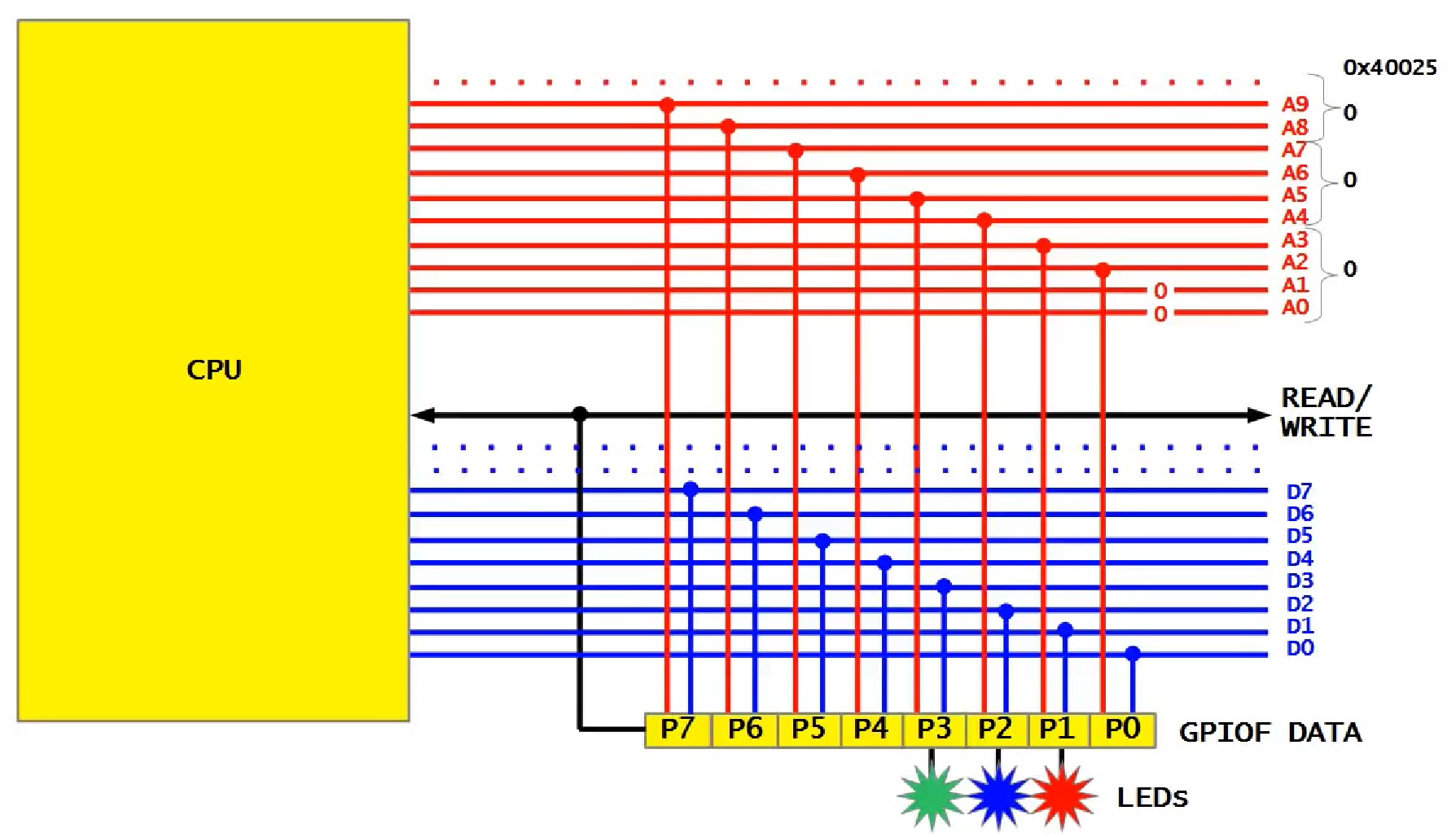
Las líneas de dirección habilitan la escritura del bit. Por tanto, si se desea escribir el bit 2 del puerto, en las
línea correspondientes del bus de direcciones debemos colocar el valor 0x010 y escribir en el bus de datos un 0x0000000004.
En los ejemplos anteriores, al ejecutar la instrucción 000003f0: F8C233FC str.w r3, [r2, #0x3fc] estamos
escribiendo el valor del registro r3 en el puerto GPIOF completo porque el valor 0x3FC en las líneas correspondientes
del bus de direcciones habilita cada bit del puerto GPIOF.
A continuación se observa el código generado por el compilador al emplear la estrategia del recurso no compartido:
1 2 3 4 | 19 GPIOF_AHB->DATA_Bits[LED_GREEN] = LED_GREEN;
000003d4: 4B0E ldr r3, [pc, #0x38]
000003d6: 2208 movs r2, #8
000003d8: 621A str r2, [r3, #0x20]
|
La instrucción ldr r3, [pc, #0x38] carga la dirección del puerto GPIOF en el registro 3 (0x4005D000), movs r2, #8
carga un 8 en r2 y finalmente str r2, [r3, #0x20] escribe un 8 en la dirección 0x4005D000 + 0x20, es decir,
se escribe un 1 en el bit 3 del puerto GPIOF correspondiente al LED verde.
El siguiente código muestra la declaración del puerto GPIOF en lenguaje C:
1 2 3 4 5 6 7 8 9 10 11 12 13 14 15 16 17 18 19 20 21 22 23 24 25 26 27 28 29 30 | typedef struct { /*!< GPIOA Structure */
__IO uint32_t DATA_Bits[255]; /*!< GPIO bit combinations */
__IO uint32_t DATA; /*!< GPIO Data */
__IO uint32_t DIR; /*!< GPIO Direction */
__IO uint32_t IS; /*!< GPIO Interrupt Sense */
__IO uint32_t IBE; /*!< GPIO Interrupt Both Edges */
__IO uint32_t IEV; /*!< GPIO Interrupt Event */
__IO uint32_t IM; /*!< GPIO Interrupt Mask */
__IO uint32_t RIS; /*!< GPIO Raw Interrupt Status */
__IO uint32_t MIS; /*!< GPIO Masked Interrupt Status */
__O uint32_t ICR; /*!< GPIO Interrupt Clear */
__IO uint32_t AFSEL; /*!< GPIO Alternate Function Select */
__I uint32_t RESERVED1[55];
__IO uint32_t DR2R; /*!< GPIO 2-mA Drive Select */
__IO uint32_t DR4R; /*!< GPIO 4-mA Drive Select */
__IO uint32_t DR8R; /*!< GPIO 8-mA Drive Select */
__IO uint32_t ODR; /*!< GPIO Open Drain Select */
__IO uint32_t PUR; /*!< GPIO Pull-Up Select */
__IO uint32_t PDR; /*!< GPIO Pull-Down Select */
__IO uint32_t SLR; /*!< GPIO Slew Rate Control Select */
__IO uint32_t DEN; /*!< GPIO Digital Enable */
__IO uint32_t LOCK; /*!< GPIO Lock */
__I uint32_t CR; /*!< GPIO Commit */
__IO uint32_t AMSEL; /*!< GPIO Analog Mode Select */
__IO uint32_t PCTL; /*!< GPIO Port Control */
__IO uint32_t ADCCTL; /*!< GPIO ADC Control */
__IO uint32_t DMACTL; /*!< GPIO DMA Control */
} GPIOA_Type;
#define GPIOF_AHB_BASE 0x4005D000UL
#define GPIOF_AHB ((GPIOA_Type *) GPIOF_AHB_BASE)
|
Más adelante veremos que existe una tercera técnica para controlar el acceso atómico o exclusivo a los recursos compartidos. Dicha opción es ofrecida por un RTOS mediante el uso semáfaros de exclusión mutua.
Ejecución de múltiples backgound concurrentes
Hasta este punto hemos ilustrado dos tipos de arquitecturas backgroud/foreground: bloqueante (espera ocupada) y no bloqueante (máquinas de estado). En este punto vamos a concentrarnos en evulucionar la versión bloqueante. Para ello, “intentaremos” crear un programa, bloqueante, que encienda y apague dos LEDs de manera independiente y concurrente. El siguiente código ilustra una intento de conseguir lo anterior:
1 2 3 4 5 6 7 8 9 10 11 12 13 14 15 16 17 18 19 20 21 | #include <stdint.h>
#include "bsp.h"
int main() {
volatile uint32_t run = 0U;
BSP_init();
while (1) {
BSP_ledGreenOn();
BSP_delay(BSP_TICKS_PER_SEC / 4U);
BSP_ledGreenOff();
BSP_delay(BSP_TICKS_PER_SEC * 3U / 4U);
BSP_ledBlueOn();
BSP_delay(BSP_TICKS_PER_SEC / 2U);
BSP_ledBlueOff();
BSP_delay(BSP_TICKS_PER_SEC / 3U);
}
//return 0;
}
|
Al ejecutar este código claramente se observa que los LEDs no están funcionando de manera concurrente e independiente. Por tanto, el siguiente evento sería tener dos ciclos:
1 2 3 4 5 6 7 8 9 10 11 12 13 14 15 16 17 18 19 20 21 22 23 24 25 26 27 28 29 30 31 32 | void main_blinky1() {
while (1) {
BSP_ledGreenOn();
BSP_delay(BSP_TICKS_PER_SEC / 4U);
BSP_ledGreenOff();
BSP_delay(BSP_TICKS_PER_SEC * 3U / 4U);
}
}
void main_blinky2() {
while (1) {
BSP_ledBlueOn();
BSP_delay(BSP_TICKS_PER_SEC / 2U);
BSP_ledBlueOff();
BSP_delay(BSP_TICKS_PER_SEC / 3U);
}
}
int main() {
volatile uint32_t run = 0U;
BSP_init();
if(run){
main_blinky1();
}
else{
main_blinky2();
}
//return 0;
}
|
Al ejecutar este código claramente se observa que sólo se ejecuta la función main_blinky2. Vamos a analizar en detalle
cómo es el funcionamiento de este programa. Para ello vamos a detener la ejecución del programa justo antes de retornar de
la interrupción SysTick_Handler`. La figura muestra el contenido del los registros del procesador, el stack frame y
el contenido del stack.
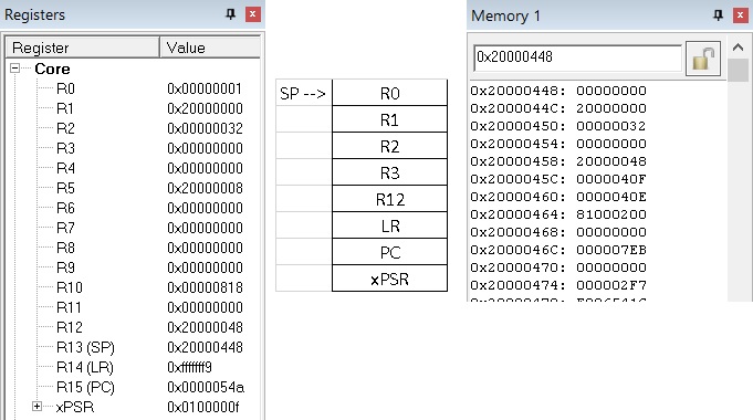
Según el stack frame y el contenido del stack, al retornar de la interrupción el programa debe continuar en la posición
de memoria PC = 0x000004EC. De manera muy astuta pregunta Juanito: ¿Y si cambiamos a mano el valor en el stack
que será cargado en el PC al retornar de la interrupción? Esto permitiría hacer que el programa continue en cualquier
posición de memoria. La siguiente figura muestra la posición en memoria de programa de la función main_blinky1:
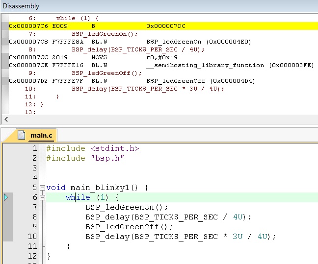
El inicio de la función está en la posición 0x000007C6. Por tanto, si modificamos la posición del stack correspondiente al PC justo antes de retornar de la interrupción, conseguiremos el efecto deseado. La siguiente figura muestra lo conseguido hasta ahora modificando de manera manual la dirección de retorno de la interrupción.
La técnica anterior es el principio sobre el cual se basan los RTOS para lograr cambiar el flujo de ejecución entre
los diferentes backgrounds disponibles. La parte del RTOS encargada de extender la arquitectura backgound/foreground
permiendo que se puedan ejecutar concurrentemente varios backgounds sobre la misma CPU se denomina kernel. A estos
múltiples backgrounds los denominamos tareas. Al proceso de cambiar frecuentemente la CPU entre mútiples tareas
creando la ilusión de que cada tarea tiene la CPU para ella sóla se denomina multitarea.
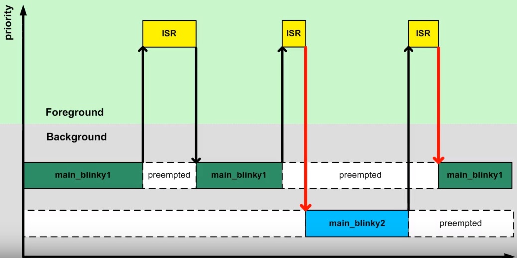
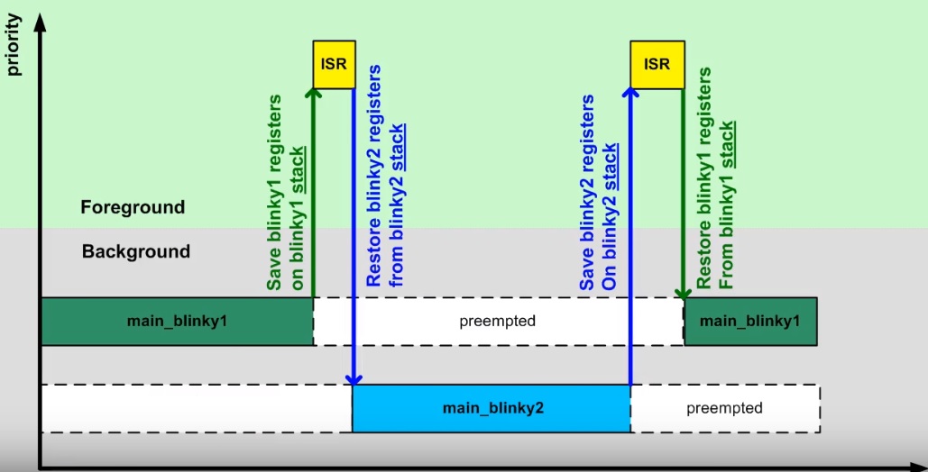
Como se señaló anteriormente, el cambio en la dirección de retorno de la interrupción es el principio de un kernel, pero
esta idea por si sola presenta un problema. Si main_blinky1 se está ejecutando y ocurre una interrupción, la CPU
salvará automáticamente los registros R0 a R3 y LR, PC y xPSR en el stack. Luego al retornar de la interrupción,
los registros serán restuardos. De esta manera la interrupción podrá hacer uso de los registros y
la función main_blinky1 podrá continuar en el punto donde fue interrumpida. Si en vez de volver a main_blinky1 el
flujo continua con main_blinky2 los registros resturados serán modificados por el código de main_blinky2 y al
retornar a main_blinky1 el estado de los registros estará corrupto. La siguiente figura ilustra el problema:
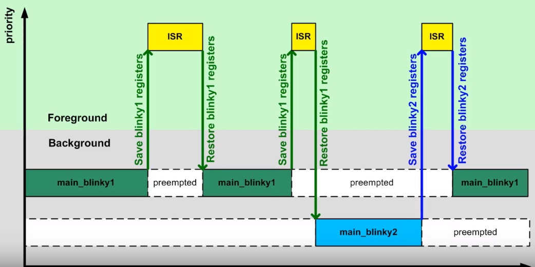
Por tanto, es necesario tener un espacio para salvar el contenido de los registros de main_blinky1, así como para main_blinky2. Si cada tarea tiene un stack propio, se puede conseguir lo que muestra la figura:
El siguiente código muestra una posible implementación para lo descrito anteriormente:
1 2 3 4 5 6 7 8 9 10 11 12 13 14 15 16 17 18 19 20 21 22 23 24 25 26 27 28 29 30 31 32 33 34 35 36 37 38 39 40 41 42 43 44 45 46 47 48 49 50 51 52 53 54 55 56 57 58 59 60 61 62 63 64 65 66 67 68 69 70 71 72 73 74 75 76 77 | #include <stdint.h>
#include "bsp.h"
#include <stdint.h>
#include "bsp.h"
uint32_t stack_blinky1[40];
uint32_t *sp_blinky1 = &stack_blinky1[40];
void main_blinky1() {
while (1) {
BSP_ledGreenOn();
BSP_delay(BSP_TICKS_PER_SEC / 4U);
BSP_ledGreenOff();
BSP_delay(BSP_TICKS_PER_SEC * 3U / 4U);
}
}
uint32_t stack_blinky2[40];
uint32_t *sp_blinky2 = &stack_blinky2[40];
void main_blinky2() {
while (1) {
BSP_ledBlueOn();
BSP_delay(BSP_TICKS_PER_SEC / 2U);
BSP_ledBlueOff();
BSP_delay(BSP_TICKS_PER_SEC / 3U);
}
}
/* background code: sequential with blocking version */
int main() {
BSP_init();
/* fabricate Cortex-M ISR stack frame for blinky1 */
*(--sp_blinky1) = (1U << 24); /* xPSR */
*(--sp_blinky1) = (uint32_t)&main_blinky1; /* PC */
*(--sp_blinky1) = 0x0000000EU; /* LR */
*(--sp_blinky1) = 0x0000000CU; /* R12 */
*(--sp_blinky1) = 0x00000003U; /* R3 */
*(--sp_blinky1) = 0x00000002U; /* R2 */
*(--sp_blinky1) = 0x00000001U; /* R1 */
*(--sp_blinky1) = 0x00000000U; /* R0 */
/* additionally, fake registers R4-R11 */
*(--sp_blinky1) = 0x0000000BU; /* R11 */
*(--sp_blinky1) = 0x0000000AU; /* R10 */
*(--sp_blinky1) = 0x00000009U; /* R9 */
*(--sp_blinky1) = 0x00000008U; /* R8 */
*(--sp_blinky1) = 0x00000007U; /* R7 */
*(--sp_blinky1) = 0x00000006U; /* R6 */
*(--sp_blinky1) = 0x00000005U; /* R5 */
*(--sp_blinky1) = 0x00000004U; /* R4 */
/* fabricate Cortex-M ISR stack frame for blinky2 */
*(--sp_blinky2) = (1U << 24); /* xPSR */
*(--sp_blinky2) = (uint32_t)&main_blinky2; /* PC */
*(--sp_blinky2) = 0x0000000EU; /* LR */
*(--sp_blinky2) = 0x0000000CU; /* R12 */
*(--sp_blinky2) = 0x00000003U; /* R3 */
*(--sp_blinky2) = 0x00000002U; /* R2 */
*(--sp_blinky2) = 0x00000001U; /* R1 */
*(--sp_blinky2) = 0x00000000U; /* R0 */
/* additionally, fake registers R4-R11 */
*(--sp_blinky2) = 0x0000000BU; /* R11 */
*(--sp_blinky2) = 0x0000000AU; /* R10 */
*(--sp_blinky2) = 0x00000009U; /* R9 */
*(--sp_blinky2) = 0x00000008U; /* R8 */
*(--sp_blinky2) = 0x00000007U; /* R7 */
*(--sp_blinky2) = 0x00000006U; /* R6 */
*(--sp_blinky2) = 0x00000005U; /* R5 */
*(--sp_blinky2) = 0x00000004U; /* R4 */
while (1) {
}
//return 0;
}
|
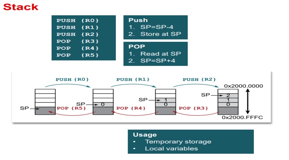
Analicemos varios asuntos del código anterior. La línea uint32_t stack_blinky1[40]; declara el stack para la tarea1.
la línea uint32_t *sp_blinky1 = &stack_blinky1[40]; inicializa el stack pointer para la tarea1. El stack es de 40
palabras de 32 bits y si inicializa en la palabra 41, es decir, una palabra por fuera del stack. La siguiente figura
ilustra el funcionamiento del stack para el microcontrolandor en cuestión e ilustra la razón para inicializar el
stack pointer de esta manera ya que al hacer una operación push primero se decrementa el stack pointer y luego
se almacena el dato en el stack.
Las siguientes líneas de código sirven para inicializar el stack de cada tarea. Note que se guardarán los registros
de la CPU xPSR,PC,LR,R0-R3, R12:
37 38 39 40 41 42 43 44 45 46 47 48 49 50 51 52 53 54 | /* fabricate Cortex-M ISR stack frame for blinky1 */
*(--sp_blinky1) = (1U << 24); /* xPSR */
*(--sp_blinky1) = (uint32_t)&main_blinky1; /* PC */
*(--sp_blinky1) = 0x0000000EU; /* LR */
*(--sp_blinky1) = 0x0000000CU; /* R12 */
*(--sp_blinky1) = 0x00000003U; /* R3 */
*(--sp_blinky1) = 0x00000002U; /* R2 */
*(--sp_blinky1) = 0x00000001U; /* R1 */
*(--sp_blinky1) = 0x00000000U; /* R0 */
/* additionally, fake registers R4-R11 */
*(--sp_blinky1) = 0x0000000BU; /* R11 */
*(--sp_blinky1) = 0x0000000AU; /* R10 */
*(--sp_blinky1) = 0x00000009U; /* R9 */
*(--sp_blinky1) = 0x00000008U; /* R8 */
*(--sp_blinky1) = 0x00000007U; /* R7 */
*(--sp_blinky1) = 0x00000006U; /* R6 */
*(--sp_blinky1) = 0x00000005U; /* R5 */
*(--sp_blinky1) = 0x00000004U; /* R4 */
|
Inicialmente ninguna de las tareas funcionará porque el programa se quedará infinitamente en el ciclo
while (1) { }. Para comenzar la ejecución de las tareas, debemos detener el programa justo antes de retornar de
SysTick_Handler. Restaruramos los registros R4-R11 (inicialmente con basura porque es la primera vez
que ejecutamos la tarea1). Ajustamos el stack pointer de la tarea 1 para que apunte a R0 y asignamos el SP de la CPU
con el valor del stack pointer de la tarea1. Una vez se reanuda el programa se debe ejecutar la tarea1.
Para ejecutar la tarea2, volvemos a detener el programa, pero esta vez al inicio de la interrupción SysTick_Handler.
En este punto, tendremos salvados en el stack de la tarea1 los registros xPSR,PC,LR,R0-R3, R12
(estos los salva la interrupción automáticamente). Ahora debemos salvar en el stack de la tarea1 el resto de registros
de la CPU, es decir, R4-R11 (comenzando por R11) y ajustar el valor del stack pointer de la tarea1 al último
registro salvado. Justo antes de retornar de la interrupción debemos restaurar los registros R4-R11 de la tarea2
(la primera vez con basura, luego si tendrá los valores apropiados), colocamos el stack pointer de la tarea2 apuntando a
R0 y asignamos el SP de la CPU con el valor del stack pointer de la tarea2. Al retornar de SysTick_Handler se
ejecutará la tarea2. Este proceso se repetirá indefinidamente. Claramente se observa que este procedimiento manual es
tedioso, pero como ya se mencionó se puede automatizar completamente por software. Ese es el trabajo del kernel del RTOS.
Ejercicio
Escriba cómo sería el algoritmo para implementar el kernel que funcione como previamente se describió. Pregunta Juanito: ¿Es posible implementar el algoritmo utilizando 100 % código C? ¿Será necesario escribir algo de código ensamblador?
Note
Los ejemplos anterior y algunas figuras son tomados de un excelente curso ofrecido por Miro Samek.
FreeRTOS
Ahora vamos a introducir el sistema operativo FreeRTOS. Haremos un recorrido por el API que ofrece este sistema opertativo de tiempo real sobre la plataforma ESP32.
Ejercicios con el API de FreeRTOS
Para realizar los siguientes ejercicio es necesario tener a la mano dos documentos:
- Tutorial oficial.
- La implementación de Espressif. ESP-FREERTOS.
Ejericio 1: explorar documentación y código fuente
Este primer ejercicio es exploratorio. Los siguientes enlaces tienen información que nos permitirá navegar por el recorrido de esta semana. Este ejercicio consiste en hojear los siguientes enlaces para hacerse a una idea de dónde encontrar la información cuando haga falta:
- Espressif, la empresa detrás de la plataforma ESP32, ha realizado un excelente trabajo de apatación del FreeRTOS al ESP32.
En los siguientes enlaces se pueden consultar los detalles:
- API de FreeRTOS: FreeRTOS.
- FreeRTOS específico para el framework ESP-IDF: FREERTOS-SMP.
- Abra cada una de las secciones del sitio con la documentación oficial del ESP32 y mire por encima.
- La página oficial de FreeRTOS.
- Manual del FreeRTOS y el tutorial oficial.
- El estándar de codificación.
- ¿Cómo funciona FreeRTOS?
- El código fuente de FreeRTOS adaptado para el ESP32 lo encontramos aquí:
esp-idf\components\freertos. No olvide darle una mirada. - Los libros oficiales de FreeRTOS vienen con ejemplos que corren en windows utilizando visual studio.
Ejercicio 2: configuración del sistema operativo
El sistema operativo se configura mediante el archivo FreeRTOSConfig.h ubicado en la ruta esp-idf\components\freertos\include\freertos.
Este archivo NO debe modificarse directamente. Para modificar el comportamiento de FreeRTOS se utiliza menuconfig en la
opción Component config ---> y luego se busca la opción FreeRTOS ---> donde se ajustará la opción deseada. Una vez
se haga el build de la aplicación, el archivo FreeRTOSConfig.h se actualizará automáticamente. Para este ejercicio haga
lo siguiente:
- Cree un directorio con el nombre FreeRTOS-example1.
- Copie los archivos del ejemplo
esp-idf\examples\get-started\hello_world.- Copie el directorio .vscode con sus configuraciones.
- Abra el directorio FreeRTOS-example1 en visual studio code (VSC)
- Compruebe que sus archivos .h son reconocidos por VSC y el
intelliSenseModefunciona.- Modifique el nombre del archivo .c en el directorio main por example1.c.
- Abra el archivo MakeFile y cambie el nombre del proyecto.
- Realice un
menuconfigpara configurar el puerto serial de la tarjeta y la velocidad de comunicación.- Realice un
build app.- Abra el archivo el archivo
FreeRTOS-example1\build\include\sdkconfig.h.- Ubique el macro
CONFIG_FREERTOS_HZ. Por defecto tendrá un valor 100, es decir, el tick del sistema será de 100 Hz- Realice de nuevo un menuconfig y modifique en el componente de FreeRTOS el tick del sistema. Coloque 1000.
- Salve y luego haga de nuevo un
build app.- Observe de nuevo
FreeRTOS-example1\build\include\sdkconfig.hy el valor de CONFIG_FREERTOS_HZ.- CONCLUYA.
Note
No olvide salvar luego de modificar una opción con menuconfig.
En relación al manejo de la memoria dinámica, tenga en cuenta que ESP-IDF utiliza las funciones malloc y free.
Si se desean utilizar las API para el manejo de los objetos de FreeRTOS con memoria estática, es necesario habilitar la
opción en menuconfig.
Ejercicio 3: manejo de tareas
La estructura de una tarea en FreeRTOS es como muestra el siguiente código:
1 2 3 4 5 6 7 | void vTaskCode( void * pvParameters )
{
for( ;; )
{
// Task code goes here.
}
}
|
Una tarea se representa en C con una función. La función NO debe retornar, pero puede recibir una dirección a cualquier
cosa. En la variable pvParameters es posible almacenar la dirección de los datos INICIALES que deseamos
pasarle a la tarea al momento de crearla.
En este ejercicio vamos a crear un par de tareas:
1 2 3 4 5 6 7 8 9 10 11 12 13 14 15 16 17 18 19 20 21 22 23 24 25 26 27 28 29 30 31 32 33 34 35 36 37 38 39 40 41 42 43 44 45 46 47 48 49 50 51 52 53 54 55 56 57 58 59 60 61 62 63 64 65 66 67 68 69 | #include <stdio.h>
#include "freertos/FreeRTOS.h"
#include "freertos/task.h"
#include "esp_system.h"
#include "esp_spi_flash.h"
/* Used as a loop counter to create a very crude delay. */
#define mainDELAY_LOOP_COUNT ( 0xffffff)
/* The task functions. */
void vTask1( void *pvParameters )
{
const char *pcTaskName = "Task 1 is running\r\n";
volatile uint32_t ul;
/* As per most tasks, this task is implemented in an infinite loop. */
for( ;; )
{
/* Print out the name of this task. */
printf( pcTaskName );
/* Delay for a period. */
for( ul = 0; ul < mainDELAY_LOOP_COUNT; ul++ )
{
/* This loop is just a very crude delay implementation. There is
nothing to do in here. Later exercises will replace this crude
loop with a proper delay/sleep function. */
}
}
}
/*-----------------------------------------------------------*/
void vTask2( void *pvParameters )
{
const char *pcTaskName = "Task 2 is running\r\n";
volatile uint32_t ul;
/* As per most tasks, this task is implemented in an infinite loop. */
for( ;; )
{
/* Print out the name of this task. */
printf( pcTaskName );
/* Delay for a period. */
for( ul = 0; ul < mainDELAY_LOOP_COUNT; ul++ )
{
/* This loop is just a very crude delay implementation. There is
nothing to do in here. Later exercises will replace this crude
loop with a proper delay/sleep function. */
}
}
}
void app_main()
{
/* Create one of the two tasks. */
xTaskCreate( vTask1, /* Pointer to the function that implements the task. */
"Task 1", /* Text name for the task. This is to facilitate debugging only. */
2048, /* Stack depth - most small microcontrollers will use much less stack than this. */
NULL, /* We are not using the task parameter. */
1, /* This task will run at priority 1. */
NULL ); /* We are not using the task handle. */
/* Create the other task in exactly the same way. */
xTaskCreate( vTask2, "Task 2", 2048, NULL, 1, NULL );
}
|
Los parámetros de xTaskCreate están detalladamente explicados aquí.
Lea detenidamente la documentación correspondiente.
Al ejecutar este código el resultado es
Task 1 is running
Task 2 is running
Task 1 is running
Task 2 is running
Task watchdog got triggered. The following tasks did not reset the watchdog in time:
- IDLE (CPU 0)
- IDLE (CPU 1)
Tasks currently running:
CPU 0: Task 1
CPU 1: Task 2
Pregunta Juanito: ¿Qué es Task watchdog? En el dominio de los sistema embebidos existe un dispositivo conocido como el perro guardián o watchdog timer. Este dispositivo se debe alimentar (feed) periódicamente, de lo contrario, reiniciará la CPU (morderá al amo). En el caso del ESP-IDF Task watchdog será una tarea más que emulará el comportamiento de un watchdog timer en software, pero no reiniciará la CPU. Pregunta Juanito: ¿Y quién alimenta al perrito? Dos tareas, cada una asociada a una CPU. Las tareas se conocemos como las Idle Tasks. Estas tareas se ejecutan cuando no hay tareas de la aplicación listas para correr porque están bloqueadas esperando por algún evento. En nuestro ejemplo, las tareas 1 y 2 están haciendo uso de las CPUs todos el tiempo en espera ocupada. Por tanto, la Task watchdog alertará al desarrollador acerca de este uso excesivo de la CPU.
Pregunta Juanito: ¿Es posible deshabilitar temporalmente Task watchdog? Sí, es necesario hacer un menuconfig e
ingresar al componente ESP32-specific donde se podrá dehabilitar la opción Initialize Task Watchdog Timer on stratup.
Realice este procedimiento y verifique de nuevo la salida del programa.
Ejercicio 4: uso de los parámetros de una tarea
En este ejercicios veremos que es posible crear tareas completamente independientes aunque utilicemos el mismo código. Es algo similar a definir una clase y luego instanciar dos objetos. Para este ejercicio podemos copiar el directorio del ejercicio anterior y hacemos lo siguiente:
Borrar el directorio build.
Borrar los archivos sdkconfig.
En .vscode dejar sólo los archivos c_cpp_properties.json y tasks.json.
Abrir el el directorio.
Cambiar el nombre del archivo .c por example2.c
En el archivo MakeFile cambiar el nombre del proyecto. Por ejemplo, FreeRTOS-exmaple2.
Abrir el archivo c_cpp_properties.json y verificar que la parte final del archivo se vea así (de lo contrario borrar):
                    "D:/ESP32/msys32/opt/xtensa-esp32-elf/lib/gcc/xtensa-esp32-elf/5.2.0/include",
                    "D:/ESP32/msys32/opt/xtensa-esp32-elf/lib/gcc/xtensa-esp32-elf/5.2.0/include-fixed"
                ],
                "limitSymbolsToIncludedHeaders": true,
                "databaseFilename": "${workspaceRoot}/.vscode/browse.vc.db"
            },
            "cStandard": "c11",
            "cppStandard": "c++17"
        }
    ],
    "version": 4
}
Hacer un menuconfig, cambiando el puerto serial, la velocidad y en
Component config,ESP32-specific, modificarPanic Handler behaviourporPrint registers and halt. De esta manera si tenemos un error podremos leer fácilmente la razón del error y las CPUs será detenidas.
Ejecutar el siguiente código:
1 2 3 4 5 6 7 8 9 10 11 12 13 14 15 16 17 18 19 20 21 22 23 24 25 26 27 28 29 30 31 32 33 34 35 36 37 38 39 40 41 42 43 44 45 46 47 48 49 50 51 52 53 54 | #include <stdio.h>
#include "freertos/FreeRTOS.h"
#include "freertos/task.h"
/* Used as a loop counter to create a very crude delay. */
#define mainDELAY_LOOP_COUNT ( 0xffffff)
/* Define the strings that will be passed in as the task parameters. These are
defined const and off the stack to ensure they remain valid when the tasks are
executing. */
const char *pcTextForTask1 = "Task 1 is running\n";
const char *pcTextForTask2 = "Task 2 is running\n";
TaskHandle_t xTask1Handle;
TaskHandle_t xTask2Handle;
/* The task function. */
void vTaskFunction( void *pvParameters )
{
char *pcTaskName;
volatile uint32_t ul;
/* The string to print out is passed in via the parameter. Cast this to a
character pointer. */
pcTaskName = (char *)pvParameters;
/* As per most tasks, this task is implemented in an infinite loop. */
for( ;; )
{
/* Print out the name of this task. */
printf( pcTaskName );
printf("stack: %d \n",uxTaskGetStackHighWaterMark(NULL));
/* Delay for a period. */
for( ul = 0; ul < mainDELAY_LOOP_COUNT; ul++ )
{
}
}
}
/*-----------------------------------------------------------*/
void app_main()
{
/* Create one of the two tasks. */
xTaskCreate( vTaskFunction, /* Pointer to the function that implements the task. */
"Task 1", /* Text name for the task. This is to facilitate debugging only. */
1000, /* Stack depth - most small microcontrollers will use much less stack than this. */
(void *) pcTextForTask1, /* Pass the text to be printed into the task using the task parameter. */
1, /* This task will run at priority 1. */
&xTask1Handle ); /* We are not using the task handle. */
/* Create the other task in exactly the same way. */
xTaskCreate( vTaskFunction, "Task 2", 1000, (void *) pcTextForTask2, 1, &xTask2Handle );
}
|
Al ejecutar la aplicación anterior y abrir el puerto serial no veremos mensajes impresos en la terminal. Si presionamos el botón de reset veremos que se ha presentado una condición de error en el programa y las CPUs se han detenido.
Ahora cambie el tamaño del stack de 1000 a 1500. ¿El mensaje de error es el mismo? Los dos errores anteriores son indicio de problemas en la definición del tamaño del stack de cada tarea. Por último, vamos a incrementar el tamaño del stack a 2048 en cada tarea. ¿Qué resultado se consigue?
Ejercicio 5: manejo de prioridades
FreeRTOS planifica las tareas (schedule) por prioridades. La política es que la CPU será entregada
a la tarea lista para correr con la prioridad más alta. Cuando las tareas tienen la misma prioridad, la CPU es entregada por
turnos (round-robin). A cada tarea se le asignará el mismo time slicing que será el intervalo entre ticks. Si
configTICK_RATE_HZ es 100 Hz cada tarea tendrá la CPU por 10 ms. Tenga presente que las prioridades se asignan
entre 0 y (configMAX_PRIORITIES – 1). El macro configMAX_PRIORITIES está definido en el archivo FreeRTOSConfig.h.
1 2 3 4 5 6 7 8 9 10 11 12 13 14 15 16 17 18 19 20 21 22 23 24 25 26 27 28 29 30 31 32 33 34 35 36 37 38 39 40 41 42 43 44 45 46 47 48 49 50 51 | #include <stdio.h>
#include "freertos/FreeRTOS.h"
#include "freertos/task.h"
/* Used as a loop counter to create a very crude delay. */
#define mainDELAY_LOOP_COUNT ( 0xffffff)
/* Define the strings that will be passed in as the task parameters. These are
defined const and off the stack to ensure they remain valid when the tasks are
executing. */
const char *pcTextForTask1 = "Task 1 is running\n";
const char *pcTextForTask2 = "Task 2 is running\n";
const char *pcTextForTask3 = "Task 3 is running\n";
/* The task function. */
void vTaskFunction( void *pvParameters )
{
char *pcTaskName;
volatile uint32_t ul;
/* The string to print out is passed in via the parameter. Cast this to a
character pointer. */
pcTaskName = (char *)pvParameters;
/* As per most tasks, this task is implemented in an infinite loop. */
for( ;; )
{
/* Print out the name of this task. */
printf( pcTaskName );
printf("stack: %d \n",uxTaskGetStackHighWaterMark(NULL));
/* Delay for a period. */
for( ul = 0; ul < mainDELAY_LOOP_COUNT; ul++ )
{
}
}
}
/*-----------------------------------------------------------*/
void app_main()
{
/* Create one of the two tasks. */
xTaskCreate( vTaskFunction, /* Pointer to the function that implements the task. */
"Task 1", /* Text name for the task. This is to facilitate debugging only. */
2048, /* Stack depth - most small microcontrollers will use much less stack than this. */
(void *) pcTextForTask1, /* Pass the text to be printed into the task using the task parameter. */
1, /* This task will run at priority 1. */
NULL ); /* We are not using the task handle. */
/* Create the other task in exactly the same way. */
xTaskCreate( vTaskFunction, "Task 2", 2048, (void *) pcTextForTask2, 2, NULL);
xTaskCreate( vTaskFunction, "Task 3", 2048, (void *) pcTextForTask3, 3, NULL );
}
|
El resultado de ejecutar el código será:
Task 2 is running
stack: 512
Task 3 is running
stack: 324
Task 2 is running
stack: 512
Task 3 is running
stack: 324
Task 2 is running
stack: 512
Pregunta Juanito: ¿Y en dónde está la tarea 1? Como la tarea 1 tiene prioridad 1, el planificador del sistema operativo
(scheduler) asignará las CPUs a las tareas 2 y 3 que tienen la prioridad más alta (2 y 3 respectivamente) y siempre
están listas para correr.
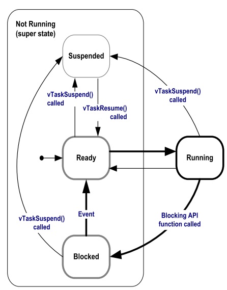
Pregunta Juanito: ¿Y cómo hacemos para que la tarea 1 pueda correr sin cambiar las prioridades? Debemos hacer que las tareas de más alta prioridad pasen del estado listas para correr a bloqueadas. Esto lo puede lograr un tarea llamando funciones especiales del sistema operativo que las obliguen a esperar por algún evento. Cuando un tarea espera por algún evento, el sistema operativo no lo tendrá en cuenta para la planificación de la CPU. Por tanto, la colocará en una lista de tareas bloqueadas (esperando por).
la siguiente figura muestra los posibles estados de una tarea en FreeRTOS:
Ejercicio 6: llamados bloqueantes
El siguiente código muestra cómo podemos modificar el ejemplo anterior, usando llamados bloqueantes, para lograr que las tareas de mayor prioridad pasen al estado bloqueado:
1 2 3 4 5 6 7 8 9 10 11 12 13 14 15 16 17 18 19 20 21 22 23 24 25 26 27 28 29 30 31 32 33 34 35 36 37 38 39 40 41 42 43 44 45 46 47 48 49 50 51 | #include <stdio.h>
#include "freertos/FreeRTOS.h"
#include "freertos/task.h"
/* Used as a loop counter to create a very crude delay. */
#define mainDELAY_LOOP_COUNT ( 0xffffff)
/* Define the strings that will be passed in as the task parameters. These are
defined const and off the stack to ensure they remain valid when the tasks are
executing. */
const char *pcTextForTask1 = "Task 1 is running\n";
const char *pcTextForTask2 = "Task 2 is running\n";
const char *pcTextForTask3 = "Task 3 is running\n";
/* The task function. */
void vTaskFunction( void *pvParameters )
{
char *pcTaskName;
/* The string to print out is passed in via the parameter. Cast this to a
character pointer. */
pcTaskName = (char *)pvParameters;
/* As per most tasks, this task is implemented in an infinite loop. */
for( ;; )
{
/* Print out the name of this task. */
printf( pcTaskName );
printf("stack: %d \n",uxTaskGetStackHighWaterMark(NULL));
/* Delay for a period. This time a call to vTaskDelay() is used which places
the task into the Blocked state until the delay period has expired. The
parameter takes a time specified in ‘ticks’, and the pdMS_TO_TICKS() macro
is used to convert 250 milliseconds into an equivalent time in ticks. */
vTaskDelay(pdMS_TO_TICKS( 1000 ));
}
}
/*-----------------------------------------------------------*/
void app_main()
{
/* Create one of the two tasks. */
xTaskCreate( vTaskFunction, /* Pointer to the function that implements the task. */
"Task 1", /* Text name for the task. This is to facilitate debugging only. */
2048, /* Stack depth - most small microcontrollers will use much less stack than this. */
(void *) pcTextForTask1, /* Pass the text to be printed into the task using the task parameter. */
1, /* This task will run at priority 1. */
NULL ); /* We are not using the task handle. */
/* Create the other task in exactly the same way. */
xTaskCreate( vTaskFunction, "Task 2", 2048, (void *) pcTextForTask2, 2, NULL);
xTaskCreate( vTaskFunction, "Task 3", 2048, (void *) pcTextForTask3, 3, NULL );
}
|
El resultado será:
Task 1 is running
stack: 600
Task 3 is running
stack: 592
Task 2 is running
stack: 532
Task 1 is running
stack: 600
Task 3 is running
stack: 592
Task 2 is running
stack: 532
Note que en este caso la tarea 1 será ejecutada. Otro llamado bloqueante que genera resultados similares es vTaskDelayUntil(). A diferencia de vTaskDelay, vTaskDelayUntil espcifica exactamente el valor del contador de ticks en el cual la tarea debe moverse del estado bloqueado al estado listo para correr. En cambio vTaskDelay especifica la cantidad de ticks que debe pasar la tarea bloqueada desde el momento en que se realiza el llamado a la función. Por tanto, si antes de llamar a vTaskDelay el código previo no es el mismo, la tarea se ejecutará con algo de jitter porque el tiempo relativo entre llamados a la función vTaskDelay presentará variabilidad (jitter).
1 2 3 4 5 6 7 8 9 10 11 12 13 14 15 16 17 18 19 20 21 22 23 24 25 26 27 28 29 30 31 32 33 34 35 36 37 38 39 40 41 42 43 44 45 46 47 48 49 50 51 52 53 54 55 56 57 58 | #include <stdio.h>
#include "freertos/FreeRTOS.h"
#include "freertos/task.h"
/* Used as a loop counter to create a very crude delay. */
#define mainDELAY_LOOP_COUNT ( 0xffffff)
/* Define the strings that will be passed in as the task parameters. These are
defined const and off the stack to ensure they remain valid when the tasks are
executing. */
const char *pcTextForTask1 = "Task 1 is running\n";
const char *pcTextForTask2 = "Task 2 is running\n";
const char *pcTextForTask3 = "Task 3 is running\n";
/* The task function. */
void vTaskFunction( void *pvParameters )
{
char *pcTaskName;
TickType_t xLastWakeTime;
/* The string to print out is passed in via the parameter. Cast this to a
character pointer. */
pcTaskName = (char *)pvParameters;
/* The xLastWakeTime variable needs to be initialized with the current tick
count. Note that this is the only time the variable is written to explicitly.
After this xLastWakeTime is automatically updated within vTaskDelayUntil(). */
xLastWakeTime = xTaskGetTickCount();
/* As per most tasks, this task is implemented in an infinite loop. */
for( ;; )
{
/* Print out the name of this task. */
printf( pcTaskName );
printf("stack: %d \n",uxTaskGetStackHighWaterMark(NULL));
/* This task should execute every 1000 milliseconds exactly. As per
the vTaskDelay() function, time is measured in ticks, and the
pdMS_TO_TICKS() macro is used to convert milliseconds into ticks.
xLastWakeTime is automatically updated within vTaskDelayUntil(), so is not
explicitly updated by the task. */
vTaskDelayUntil( &xLastWakeTime, pdMS_TO_TICKS( 1000 ));
}
}
/*-----------------------------------------------------------*/
void app_main()
{
/* Create one of the two tasks. */
xTaskCreate( vTaskFunction, /* Pointer to the function that implements the task. */
"Task 1", /* Text name for the task. This is to facilitate debugging only. */
2048, /* Stack depth - most small microcontrollers will use much less stack than this. */
(void *) pcTextForTask1, /* Pass the text to be printed into the task using the task parameter. */
1, /* This task will run at priority 1. */
NULL ); /* We are not using the task handle. */
/* Create the other task in exactly the same way. */
xTaskCreate( vTaskFunction, "Task 2", 2048, (void *) pcTextForTask2, 2, NULL);
xTaskCreate( vTaskFunction, "Task 3", 2048, (void *) pcTextForTask3, 3, NULL );
}
|
El resultado debe ser el mismo del código anterior.
Más ejercicios con el API de FreeRTOS
Para realizar los siguientes ejercicio es necesario tener a la mano dos documentos:
- Tutorial oficial.
- La implementación de Espressif. ESP-FREERTOS.
Ejericio 1: comunicación entre tareas
Las colas o Queues son uno de los mecanismos de comunicación de FreeRTOS. Estas permiten comunicar tareas, tareas con interrupciones e interrupiones con tareas.
Las colcas almacenan una cantidad finita de items todos ellos del mismo tamaño. La longitud de la cola es la cantidad máxima de items que puede almacenar. Al momento de crear la cola se define el tamaño de los items y la longitud de la cola.
Las colas se utilizan como estructuras de datos FIFO (First In First Out). Los datos se escriben al final de la cola (tail) y se remueven del frente (head). Es posible escribir al frente de la cola para modificar datos que ya están presentes.
La siguiente figura ilustra cómo funciona una cola:
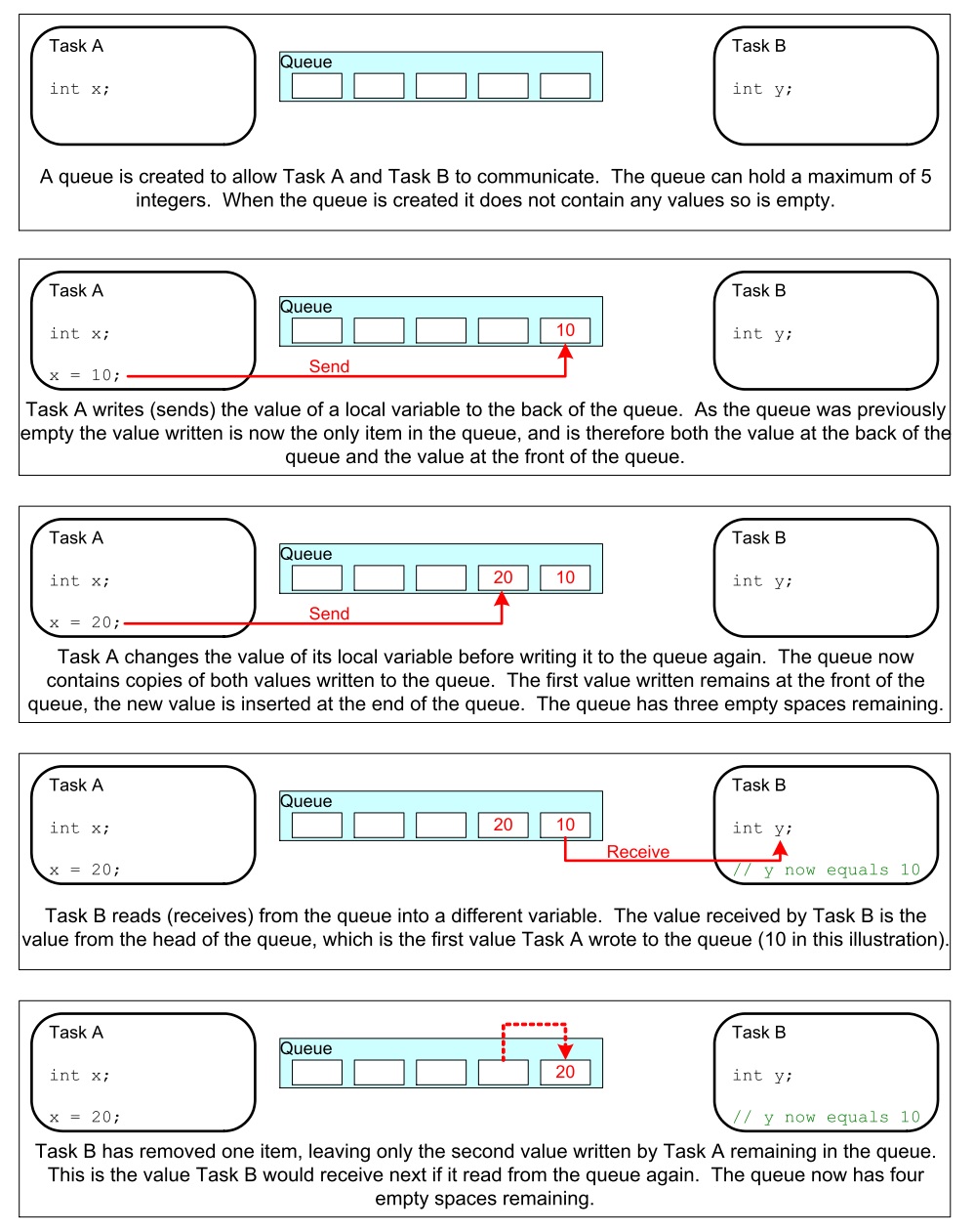
Los datos que se almacenan en la cola pueden comportarse por valor (copia byte por byte) o por referencia (se copia la dirección del puntero donde están los datos). El primer método es más costoso en términos de memoria, pero permite desacoplar mejor las tareas, haciendo más simple el manejo de la información.
Otras características a considerar:
Es usual que una cola tenga múltiples escritores y sólo un lector. Aún así, es posible usarlas con otros esquemas.
Una tarea lectora se bloqueará si no hay datos en la cola. Es posible especificar el tiempo que durará bloqueada. Si otra tarea o una interrupción envía datos a la cola, la tarea pasará automáticamente al estado lista para ejecución y por tanto será candidata a tener una CPU cuando el scheduler así lo determine.
Las tareas pueden bloquerse, y especificar también tiempos de bloqueo, al escribir una cola. Esto ocurre cuando no hay más espacio disponible.
Varias tareas escritoras pueden bloquearse al esperar espacio en una cola. Cuando el espacio esté disponible, la tarea de más alta prioridad será desbloqueada y puesta en lista para correr. Si todas las tareas tienen la misma prioridad, la tarea que lleve más tiempo esperando desbloqueada y puesta lista para correr.
API para crear una cola
QueueHandle_t xQueueCreate( UBaseType_t uxQueueLength, UBaseType_t uxItemSize );
Actividades:
- Realizar el ejemplo 10 del Tutorial oficial.
- Realizar el ejemplo 11.
Recuerde que en ambas actividades es de esperar un comportamiento diferente gracias a los dos CPUs. De igual manera, es necesario adaptar el código pues no tenemos acceso directo a la función main. Pregunta juanito: ¿Cómo adapto el código? Mire los ejemplos anteriores y compárelos con los códigos de la semana 3.
Ejericio 2: verificación del ejemplo 10
Una vez realizado el ejercicio 1 compare su respuesta con el siguiente código. Analice y concluya:
1 2 3 4 5 6 7 8 9 10 11 12 13 14 15 16 17 18 19 20 21 22 23 24 25 26 27 28 29 30 31 32 33 34 35 36 37 38 39 40 41 42 43 44 45 46 47 48 49 50 51 52 53 54 55 56 57 58 59 60 61 62 63 64 65 66 67 68 69 70 71 72 73 74 75 76 77 78 79 80 81 82 83 84 85 86 87 88 89 90 91 92 93 94 95 96 97 98 99 100 101 102 103 104 105 106 107 108 109 110 111 112 113 114 115 | #include <stdio.h>
#include "freertos/FreeRTOS.h"
#include "freertos/task.h"
#include "freertos/queue.h"
/*-----------------------------------------------------------*/
/* Declare a variable of type QueueHandle_t. This is used to store the handle
to the queue that is accessed by all three tasks. */
QueueHandle_t xQueue;
static void vSenderTask( void *pvParameters )
{
int32_t lValueToSend;
BaseType_t xStatus;
/* Two instances of this task are created so the value that is sent to the
queue is passed in via the task parameter - this way each instance can use
a different value. The queue was created to hold values of type int32_t,
so cast the parameter to the required type. */
lValueToSend = ( int32_t ) pvParameters;
/* As per most tasks, this task is implemented within an infinite loop. */
for( ;; )
{
/* Send the value to the queue.
The first parameter is the queue to which data is being sent.
The second parameter is the address of the data to be sent, in this case
the address of lValueToSend.
The third parameter is the Block time – the time the task should be kept
in the Blocked state to wait for space to become available on the queue.
*/
printf( "Sender(%d). stack: %d\r\n",lValueToSend,uxTaskGetStackHighWaterMark(NULL));
xStatus = xQueueSendToBack( xQueue, &lValueToSend, 0 );
if( xStatus != pdPASS )
{
/* The send operation could not complete because the queue was full - */
printf( "Could not send to the queue.\r\n" );
}
}
}
static void vReceiverTask( void *pvParameters )
{
/* Declare the variable that will hold the values received from the queue. */
int32_t lReceivedValue;
BaseType_t xStatus;
const TickType_t xTicksToWait = pdMS_TO_TICKS( 100 );
/* This task is also defined within an infinite loop. */
for( ;; )
{
printf( "There are (%d) messages waiting\r\n",uxQueueMessagesWaiting( xQueue ));
/* Receive data from the queue.
The first parameter is the queue from which data is to be received.
The second parameter is the buffer into which the received data will be
placed. In this case the buffer is simply the address of a variable that
has the required size to hold the received data.
The last parameter is the block time – the maximum amount of time that the
task will remain in the Blocked state to wait for data to be available */
printf("Receiver stack: %d\r\n",uxTaskGetStackHighWaterMark(NULL));
xStatus = xQueueReceive( xQueue, &lReceivedValue, xTicksToWait );
if( xStatus == pdPASS )
{
/* Data was successfully received from the queue, print out the received
value. */
printf( "Received = %d\r\n", lReceivedValue );
}
else
{
/* Data was not received from the queue even after waiting for 100ms.
This must be an error as the sending tasks are free running and will be
continuously writing to the queue. */
printf( "After 100ms blocking time, could not receive from the queue.\r\n" );
}
}
}
void app_main()
{
/* The queue is created to hold a maximum of 5 values, each of which is
large enough to hold a variable of type int32_t. */
xQueue = xQueueCreate( 5, sizeof( int32_t ) );
if( xQueue != NULL )
{
/* Create the task that will read from the queue. The task is created with
priority 2, so above the priority of the sender tasks. */
xTaskCreate( vReceiverTask, "Receiver", 2048, NULL, 2, NULL );
/* Create two instances of the task that will send to the queue. The task
parameter is used to pass the value that the task will write to the queue,
so one task will continuously write 100 to the queue while the other task
will continuously write 200 to the queue. Both tasks are created at
priority 1. */
xTaskCreate( vSenderTask, "Sender1", 2048, ( void * ) 100, 1, NULL );
xTaskCreate( vSenderTask, "Sender2", 2048, ( void * ) 200, 1, NULL );
}
else
{
/* The queue could not be created. */
}
}
|
Al ejecutar el código
There are (0) messages waiting
Sender(100). stack: 1756
Receiver stack: 512
Sender(200). stack: 1752
Received = 100
Sender(100). stack: 588
There are (1) messages waiting
Sender(200). stack: 584
Receiver stack: 512
Received = 200
There are (2) messages waiting
Sender(200). stack: 584
Receiver stack: 512
Received = 100
There are (2) messages waiting
Sender(200). stack: 584
Receiver stack: 512
Received = 200
There are (2) messages waiting
Sender(200). stack: 584
Receiver stack: 512
Received = 200
There are (2) messages waiting
Sender(200). stack: 584
Receiver stack: 512
Received = 200
There are (2) messages waiting
Sender(200). stack: 520
Receiver stack: 512
Received = 200
Luego de un instante aquí hay otra captura de la salida
There are (2) messages waiting
Sender(100). stack: 588
Receiver stack: 512
Received = 200
There are (2) messages waiting
Sender(100). stack: 588
Receiver stack: 512
Received = 200
There are (2) messages waiting
Sender(100). stack: 588
Receiver stack: 512
Received = 100
There are (2) messages waiting
Sender(100). stack: 588
Receiver stack: 512
Received = 100
There are (2) messages waiting
Sender(100). stack: 588
Receiver stack: 512
Received = 100
There are (2) messages waiting
Sender(100). stack: 524
Receiver stack: 512
Received = 100
There are (2) messages waiting
Note cómo la ejecución de las tarea que envían se alterna en el tiempo.
Ejericio 3: verificación del ejemplo 11
En el ejemplo 11 del tutorial, una tarea lectora recibe mensajes de varias tareas escritoras. Todos los mensajes llegan a la misma cola, por tanto, es necesario establecer una estrategia que permita identificar la fuente de cada mensaje. El escenario que se describe se ilustra en la siguiente figura:
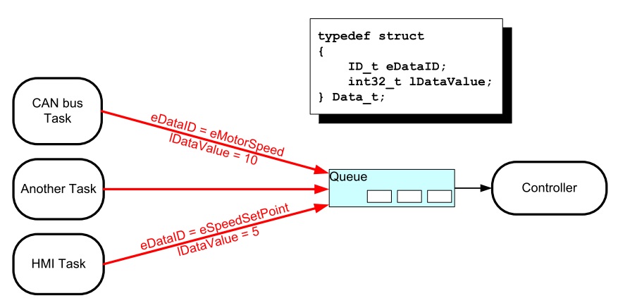
Aquí está el código del ejemplo 11:
1 2 3 4 5 6 7 8 9 10 11 12 13 14 15 16 17 18 19 20 21 22 23 24 25 26 27 28 29 30 31 32 33 34 35 36 37 38 39 40 41 42 43 44 45 46 47 48 49 50 51 52 53 54 55 56 57 58 59 60 61 62 63 64 65 66 67 68 69 70 71 72 73 74 75 76 77 78 79 80 81 82 83 84 85 86 87 88 89 90 91 92 93 94 95 | #include <stdio.h>
#include "freertos/FreeRTOS.h"
#include "freertos/task.h"
#include "freertos/queue.h"
/* The tasks to be created. Two instances are created of the sender task while
only a single instance is created of the receiver task. */
static void vSenderTask( void *pvParameters );
static void vReceiverTask( void *pvParameters );
/* Declare a variable of type QueueHandle_t. This is used to store the queue
that is accessed by all three tasks. */
QueueHandle_t xQueue;
typedef enum
{
eSender1,
eSender2
} DataSource_t;
/* Define the structure type that will be passed on the queue. */
typedef struct
{
uint8_t ucValue;
DataSource_t eDataSource;
} Data_t;
/* Declare two variables of type Data_t that will be passed on the queue. */
static const Data_t xStructsToSend[ 2 ] =
{
{ 100, eSender1 }, /* Used by Sender1. */
{ 200, eSender2 } /* Used by Sender2. */
};
void app_main(void)
{
xQueue = xQueueCreate( 3, sizeof( Data_t ) );
if( xQueue != NULL )
{
xTaskCreate( vSenderTask, "Sender1", 2048, ( void * ) &( xStructsToSend[ 0 ] ), 2, NULL );
xTaskCreate( vSenderTask, "Sender2", 2048, ( void * ) &( xStructsToSend[ 1 ] ), 2, NULL );
xTaskCreate( vReceiverTask, "Receiver", 2048, NULL, 1, NULL );
}
else
{
printf("The queue could not be created.\r\n");
}
}
/*-----------------------------------------------------------*/
static void vSenderTask( void *pvParameters )
{
BaseType_t xStatus;
const TickType_t xTicksToWait = pdMS_TO_TICKS( 100UL );
for( ;; )
{
xStatus = xQueueSendToBack( xQueue, pvParameters, xTicksToWait );
if( xStatus != pdPASS )
{
printf( "After 100ms blocking time, could not send to the queue.\r\n" );
}
}
}
/*-----------------------------------------------------------*/
static void vReceiverTask( void *pvParameters )
{
Data_t xReceivedStructure;
BaseType_t xStatus;
for( ;; )
{
printf( "There are (%d) messages waiting\r\n",uxQueueMessagesWaiting( xQueue ));
xStatus = xQueueReceive( xQueue, &xReceivedStructure, 0 );
if( xStatus == pdPASS )
{
if( xReceivedStructure.eDataSource == eSender1 )
{
printf( "From Sender 1 = %d\r\n", xReceivedStructure.ucValue );
}
else
{
printf( "From Sender 2 = %d\r\n", xReceivedStructure.ucValue );
}
}
else
{
printf( "The queue is empty.\r\n" );
}
}
}
|
Y el resultado es:
There are (3) messages waiting
From Sender 1 = 100
There are (3) messages waiting
From Sender 1 = 100
There are (3) messages waiting
From Sender 1 = 100
There are (3) messages waiting
From Sender 1 = 100
There are (3) messages waiting
From Sender 2 = 200
There are (3) messages waiting
From Sender 1 = 100
There are (3) messages waiting
From Sender 2 = 200
There are (3) messages waiting
From Sender 1 = 100
There are (3) messages waiting
From Sender 2 = 200
There are (3) messages waiting
From Sender 1 = 100
There are (3) messages waiting
From Sender 2 = 200
Analice el resultado. ¿Qué puede concluir?
Ejercicio 4: ¡RETO!
En este ejercicio se requiere resolver el siguiente reto. Debemos comunicar dos tareas. La tarea escritora enviará mensajes de longitud variable. Cada mensaje será una cadena. La tarea lectora deberá imprimir los mensajes recibidos. Por su parte la tarea escritora deberá crear un buffer (sólo uno) con el tamaño apropiado para poder alojar cada mensaje. Los mensajes serán enviados por medio de una cola. Cada mensaje en la cola debe tener un puntero al buffer donde está el mensaje. Tenga presente que el escritor no podrá utilizar el buffer hasta que el lector lea el mensaje y lo imprima. Por tanto es necesario pensar en una estrategia para sincronizar las tareas.
Ejercicio 5: Software Timers
Los software timers se utilizan para programar la ejecución de una función ( callback ) en un instante de tiempo futuro o de manera periódica a una frecuencia fija. Hay dos tipos de software timers: one-shot timer y periódico o auto-reload timer. En el primero, el callback se ejecuta sólo una vez. En el segundo, el callback se llama periódicamente. Un software timer puede estar en uno de dos posibles estados: dormant, no está corriendo y su callback no será ejecutado, running, está corriendo y su callback será ejecutado. La siguiente figura muestra el modelo de funcionamiento de un auto-reload timer:
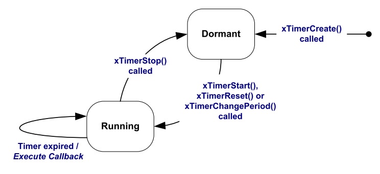
La siguiente figura muestra el modelos de funcionamiento de un one-shot timer:
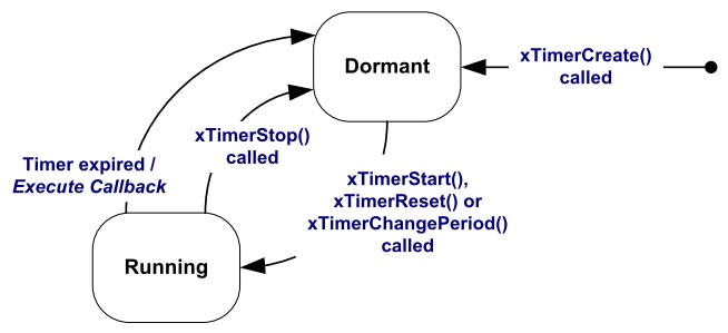
Al utilizar los software timers se debe considerar:
Es necesario incluir freertos/timers.h
Declarar el callback usando el siguiente prototipo:
void ATimerCallback( TimerHandle_t xTimer );
Los callback se ejecutan de principio a fin. Deben mantenerse cortos y NUNCA entrar en estado bloqueado.
Los callback ejecutan en el contexto de una tarea que FreeRTOS crea automáticamente al iniciar. Por tanto, no deben hacer llamados a funciones bloqueantes que puedan bloquear la tarea creada por FreeRTOS.
Es posible utilizar funciones como xQueueReceive, pero se debe definir el tiempo de bloqueo en 0.
Todos los software timers se ejecutan en el contexto de una tarea, timer service task, de FreeRTOS que se crea automáticamente cuando el scheduler inicia. El tamaño de su stack y prioridad se definen utilizando menuconfig. Para evitar que la tarea timer service se bloquee no se pueden utilizar servicios bloqueantes de FreeRTOS.
La comunicación entre las tareas que crean software timers y la tarea timer service se realiza mediante una cola de comandos, tales como: start, stop, reset. La cola es creada automáticamente cuando el planificador inicia. El tamaño de la cola se define con menuconfig. Los comandos son eviados a la cola usando funciones especificas del API de FreeRTOS.
API.
Para el ejercicio la configuración por defecto de la tarea timer service es:
- Prioridad: 1
- Tamaño del stack: 2048
- Tamaño de la cola: 10
El siguiente código ilustra el uso de los dos tipos de software timer:
1 2 3 4 5 6 7 8 9 10 11 12 13 14 15 16 17 18 19 20 21 22 23 24 25 26 27 28 29 30 31 32 33 34 35 36 37 38 39 40 41 42 43 44 45 46 47 48 49 50 51 52 53 54 55 56 57 58 59 60 61 62 63 64 65 66 67 68 69 70 71 72 73 74 75 76 | #include <stdio.h>
#include "freertos/FreeRTOS.h"
#include "freertos/task.h"
#include "freertos/queue.h"
#include "freertos/timers.h"
/* The periods assigned to the one-shot and auto-reload timers respectively. */
#define mainONE_SHOT_TIMER_PERIOD ( pdMS_TO_TICKS( 3333UL ) )
#define mainAUTO_RELOAD_TIMER_PERIOD ( pdMS_TO_TICKS( 500UL ) )
/*-----------------------------------------------------------*/
/*
* The callback functions used by the one-shot and auto-reload timers
* respectively.
*/
static void prvOneShotTimerCallback( TimerHandle_t xTimer );
static void prvAutoReloadTimerCallback( TimerHandle_t xTimer );
void app_main(void){
TimerHandle_t xAutoReloadTimer, xOneShotTimer;
BaseType_t xTimer1Started, xTimer2Started;
/* Create the one shot software timer, storing the handle to the created
software timer in xOneShotTimer. */
xOneShotTimer = xTimerCreate( "OneShot", mainONE_SHOT_TIMER_PERIOD,
pdFALSE, 0, prvOneShotTimerCallback );
/* Create the auto-reload software timer, storing the handle to the created
software timer in xAutoReloadTimer. */
xAutoReloadTimer = xTimerCreate( "AutoReload", mainAUTO_RELOAD_TIMER_PERIOD,
pdTRUE, 0, prvAutoReloadTimerCallback );
/* Check the timers were created. */
if( ( xOneShotTimer != NULL ) && ( xAutoReloadTimer != NULL ) )
{
/* Start the software timers, using a block time of 0 (no block time). */
xTimer1Started = xTimerStart( xOneShotTimer, 0 );
xTimer2Started = xTimerStart( xAutoReloadTimer, 0 );
/* The implementation of xTimerStart() uses the timer command queue, and
xTimerStart() will fail if the timer command queue gets full.
Check both calls to xTimerStart() passed. */
if( ( xTimer1Started == pdPASS ) && ( xTimer2Started == pdPASS ) )
{
/* Start the scheduler. */
printf("Timers are started\r\n");
}
}
}
/*-----------------------------------------------------------*/
static void prvOneShotTimerCallback( TimerHandle_t xTimer )
{
static TickType_t xTimeNow;
/* Obtain the current tick count. */
xTimeNow = xTaskGetTickCount();
/* Output a string to show the time at which the callback was executed. */
printf( "One-shot timer callback executing %d\r\n", xTimeNow );
}
/*-----------------------------------------------------------*/
static void prvAutoReloadTimerCallback( TimerHandle_t xTimer )
{
static TickType_t xTimeNow;
/* Obtain the current tick count. */
xTimeNow = xTaskGetTickCount();
/* Output a string to show the time at which the callback was executed. */
printf( "Auto-reload timer callback executing %d\r\n", xTimeNow );
}
/*-----------------------------------------------------------*/
|
El resultado de ejecutar el programa:
Timers are started
Auto-reload timer callback executing 50
Auto-reload timer callback executing 100
Auto-reload timer callback executing 150
Auto-reload timer callback executing 200
Auto-reload timer callback executing 250
Auto-reload timer callback executing 300
One-shot timer callback executing 333
Auto-reload timer callback executing 350
Auto-reload timer callback executing 400
Auto-reload timer callback executing 450
Continua el camino por el API de FreeRTOS
Ya casi tenemos todos los elementos básicos para comenzar a realizar aplicaciones. Es bueno aclarar en este punto que hay muchos más detalles del API que hemos dejado de lado, por tanto, aún más camino por recorrer en el futuro.
Consideraciones del material anteriore
Reto anterior
Una posible solución al reto anterior es:
1 2 3 4 5 6 7 8 9 10 11 12 13 14 15 16 17 18 19 20 21 22 23 24 25 26 27 28 29 30 31 32 33 34 35 36 37 38 39 40 41 42 43 44 45 46 47 48 49 50 51 52 53 54 55 56 57 58 59 60 61 62 63 64 65 66 67 68 69 70 | #include <stdio.h>
#include <string.h>
#include "freertos/FreeRTOS.h"
#include "freertos/task.h"
#include "freertos/queue.h"
#include "freertos/portmacro.h"
static void vSenderTask( void *pvParameters );
static void vReceiverTask( void *pvParameters );
QueueHandle_t xQueueMessage;
QueueHandle_t xQueueACK;
char * messages[] = {"Hola mundo" ,
"Cruel y despiadado",
"La vida es bella, el feo es uno",
"Hay 10 tipos de personas en el mundo: los que entienden el binario, y los que no",
"Por favor envie todo el spam a mi direccion principal, root@localhost"};
void app_main(void)
{
xQueueMessage = xQueueCreate( 1, sizeof( char * ) );
xQueueACK = xQueueCreate( 1, sizeof( uint8_t ) );
if( (xQueueMessage != NULL) &&(xQueueACK != NULL) )
{
xTaskCreate( vSenderTask, "Sender", 2048, NULL, 2, NULL );
xTaskCreate( vReceiverTask, "Receiver", 2048, NULL, 2, NULL );
}
else
{
printf("The queues could not be created.\r\n");
}
}
/*-----------------------------------------------------------*/
static void vSenderTask( void *pvParameters )
{
UBaseType_t msgIndex = 0;
char buffer[100];
char *pbuffer = buffer;
uint8_t ack = 0;
for( ;; )
{
//printf("Sending message... %d\r\n",msgIndex);
strcpy (buffer,messages[msgIndex]);
msgIndex = (msgIndex + 1) % (sizeof(messages)/sizeof(messages[0]));
xQueueSendToBack( xQueueMessage, &pbuffer, portMAX_DELAY );
xQueueReceive( xQueueACK, &ack, portMAX_DELAY);
vTaskDelay(pdMS_TO_TICKS(1000));
}
}
/*-----------------------------------------------------------*/
static void vReceiverTask( void *pvParameters )
{
char * pbuffer;
portCHAR ack = 1;
for( ;; )
{
//printf( "Waiting message...\r\n");
xQueueReceive( xQueueMessage, &pbuffer, portMAX_DELAY);
printf("Message: %s\r\n",pbuffer);
xQueueSendToBack( xQueueACK, &ack, portMAX_DELAY );
}
}
|
El resultados sera:
Message: Hola mundo
Message: Cruel y despiadado
Message: La vida es bella, el feo es uno
Message: Hay 10 tipos de personas en el mundo: los que entienden el binario, y los que no
Message: Por favor envie todo el spam a mi direccion principal, root@localhost
El código anterior tiene varias cosas interesante:
- La línea
xQueueMessage = xQueueCreate( 1, sizeof( char * ) );crea una cola de tamaño 1. El item es de 4 bytes, correspondientes al tamaño de las direcciones en el ESP-32 (sizeof(char *)). En este caso la idea es que el item de la cola almacenará la dirección del buffer con los caráctares del mensaje. msgIndex = (msgIndex + 1) % (sizeof(messages)/sizeof(messages[0]));Incrementa el índice de mensajes haciendo que al llegar a la cantidad de items contenidos en el arreglo de mensajes, se reinicie el conteo a 0 gracias a la función módulo (%).char *pbuffer = buffer;almacena la dirección del buffer con los caracteres.- En
xQueueSendToBack( xQueueMessage, &pbuffer, portMAX_DELAY );&pbufferpasa la dirección de una variable que contendrá el valor del item a enviar. En este caso, el valor es una dirección, es decir, la dirección en memoria donde están los caracteres con el mensaje. - Al
xQueueReceive( xQueueMessage, &pbuffer, portMAX_DELAY);se pasa la dirección de una variable donde se almecenará la dirección en memoria del buffer de caracteres.
Sobre la función app_main
Pregunta Juanito: ¿Qué es app_main? app_main es una función llamada por el framework ESP-IDF. Esta función es llamada
por la tarea principal:
1 2 3 4 5 6 7 8 9 10 11 12 13 14 15 16 17 18 19 20 21 22 23 24 25 26 27 28 29 30 31 32 33 34 35 36 37 38 39 | static void main_task(void* args)
{
// Now that the application is about to start, disable boot watchdogs
REG_CLR_BIT(TIMG_WDTCONFIG0_REG(0), TIMG_WDT_FLASHBOOT_MOD_EN_S);
REG_CLR_BIT(RTC_CNTL_WDTCONFIG0_REG, RTC_CNTL_WDT_FLASHBOOT_MOD_EN);
#if !CONFIG_FREERTOS_UNICORE
// Wait for FreeRTOS initialization to finish on APP CPU, before replacing its startup stack
while (port_xSchedulerRunning[1] == 0) {
;
}
#endif
//Enable allocation in region where the startup stacks were located.
heap_caps_enable_nonos_stack_heaps();
//Initialize task wdt if configured to do so
#ifdef CONFIG_TASK_WDT_PANIC
ESP_ERROR_CHECK(esp_task_wdt_init(CONFIG_TASK_WDT_TIMEOUT_S, true))
#elif CONFIG_TASK_WDT
ESP_ERROR_CHECK(esp_task_wdt_init(CONFIG_TASK_WDT_TIMEOUT_S, false))
#endif
//Add IDLE 0 to task wdt
#ifdef CONFIG_TASK_WDT_CHECK_IDLE_TASK_CPU0
TaskHandle_t idle_0 = xTaskGetIdleTaskHandleForCPU(0);
if(idle_0 != NULL){
ESP_ERROR_CHECK(esp_task_wdt_add(idle_0))
}
#endif
//Add IDLE 1 to task wdt
#ifdef CONFIG_TASK_WDT_CHECK_IDLE_TASK_CPU1
TaskHandle_t idle_1 = xTaskGetIdleTaskHandleForCPU(1);
if(idle_1 != NULL){
ESP_ERROR_CHECK(esp_task_wdt_add(idle_1))
}
#endif
app_main();
vTaskDelete(NULL);
}
|
Antes de llegar aquí han ocurrido los siguientes pasos:
- La CPU 0 o PRO_CPU inicia en la posición de memoria
0x40000400correspondiente al vector de reset del chip. - En este punto la CPU 1 o APP_CPU está en estado de reset.
- Una vez inicia la PRO_CPU se ejecuta el primer bootloader, cargado por el fabricante del chip. La función de ese bootloader
es cargar un segundo bootloader, residente en la posición
0x1000, con más funciones que el primero y cuyo código fuente se puede consultar el directoriocomponents/bootloader. El concepto de segundo bootloader permite hacer cosas como leer la tabla de particiones de la flash, implementar estrategias de encriptado de la memoria, ejecutar un proceso de carga segura de la aplicación, secure boot, y hacer actualizaciones del programa tipoover-the-airuOTA. - Espressif entrega como parte del ESP-IDF el bootloader anterior. Por tanto, es posible modificarlo completamente o cambiar su funcionamiento.
- El segundo
bootloaderlee la tabla de particiones y decide cuál aplicación cargar. Aquí es donde ocurre la majia de seleccionar entre una aplicación nueva (actualización mediante OTA) o seguir con la aplicación anterior. - El segundo bootloader también se encarga de cargar partes de la aplicación en la
IRAM(instruction RAM) oDRAM(data RAM) así como configurar las zonas de la FLASH utilizadas como IROM (instruction ROM) o DROM (data ROM). - Finalmente el segundo bootloader le entrega el control a la aplicación.
- El punto de entrada de la aplicación es
call_start_cpu0ubicado encomponents/esp32/cpu_start.c. - En
call_start_cpu0se inicia la APP_CPU que ejecutará la funcióncall_start_cpu1. Finalmente PRO_CPU saltarástart_cpu0y APP_CPU astart_cpu1. Estas de últimas funciones iniciarán el planificador en cada CPU y se creará la tareamain_taskquien finalmente llamará el punto de entrada del código de usuario que será la funciónapp_main. - Una vez se retorne de
app_mainla tareamain_taskterminará y será borrada. - Se pueden leer más detalles de este proceso aquí.
Ejercicios con el API de FreeRTOS
Para realizar los siguientes ejercicio es necesario tener a la mano dos documentos:
- Tutorial oficial.
- La implementación de Espressif. ESP-FREERTOS.
Ejercicio 1: memoria de aplicación
El código y datos de la aplicación pueden ubicarse en varias regiones de memoria: IRAM, IROM, RTC fast memory,
DRAM, DROM, RTC slow memory.
Para indicarle al enlazador (linker) que ubique códígo en la IRAM se utiliza el atributo IRAM_ATTR:
#include "esp_attr.h"

void IRAM_ATTR gpio_isr_handler(void* arg)
{
        // ...
}
La definición de un servicios de atención a interrupción es un uso típico de lo anterior. Otro caso, son las funciones del API de FreeRTOS.
Por otra parte, Si una función, explícitamente, no se ubica en IRAM o en RTC, se colocará en flash, es decir, IROM.
En la región RTC fast memory, debe ubicarse el código que se ejecutará luego de despartar de una condición de
Deep sleep.
La datos constantes de la aplicación se pueden colocan en la DRAM utilizando el atributo DRAM_ATTR:
DRAM_ATTR const char[] format_string = "%p %x";
char buffer[64];
sprintf(buffer, format_string, ptr, val);
Por defecto las constantes se ubican en la DROM. Las constantes literales se embeben en el propio código de la aplicación.
Finalmente, en RTC slow memory se ubican las variables estáticas globales y globales que serán usadas desde la
memoria RTC, así:
RTC_NOINIT_ATTR uint32_t rtc_noinit_data;
Ejericio 2: comunicación entre interrupciones y tareas
Para este ejercicio vamos a conectar dos puertos de entrada con dos puertos de salida del microcontrolador.
Los puertos de entrada capturarán el cambio de nivel de voltaje en las salidas así: GPIO5 flancos de subida, GPIO4
flancos de subida y bajada. Los eventos anteriores serán enviados, desde un servicio de atención a interrupción,
a una tarea utilizando una cola. A esta técnica de tratamiento de las interrupciones se le conoce como PROCESAMIENTO
DIFERIDO DE INTERRUPCIONES. El código del ejemplo es el siguiente:
1 2 3 4 5 6 7 8 9 10 11 12 13 14 15 16 17 18 19 20 21 22 23 24 25 26 27 28 29 30 31 32 33 34 35 36 37 38 39 40 41 42 43 44 45 46 47 48 49 50 51 52 53 54 55 56 57 58 59 60 61 62 63 64 65 66 67 68 69 70 71 72 73 74 75 76 77 78 79 80 81 82 83 84 85 86 87 88 89 90 91 92 93 94 95 96 97 98 99 100 101 102 103 104 105 106 107 108 109 110 111 112 113 | /* GPIO Example
This example code is in the Public Domain (or CC0 licensed, at your option.)
Unless required by applicable law or agreed to in writing, this
software is distributed on an "AS IS" BASIS, WITHOUT WARRANTIES OR
CONDITIONS OF ANY KIND, either express or implied.
*/
#include <stdio.h>
#include <string.h>
#include <stdlib.h>
#include "freertos/FreeRTOS.h"
#include "freertos/task.h"
#include "freertos/queue.h"
#include "driver/gpio.h"
/**
* Brief:
* This test code shows how to configure gpio and how to use gpio interrupt.
*
* GPIO status:
* GPIO18: output
* GPIO19: output
* GPIO4: input, pulled up, interrupt from rising edge and falling edge
* GPIO5: input, pulled up, interrupt from rising edge.
*
* Test:
* Connect GPIO18 with GPIO4
* Connect GPIO19 with GPIO5
* Generate pulses on GPIO18/19, that triggers interrupt on GPIO4/5
*
*/
#define GPIO_OUTPUT_IO_0 18
#define GPIO_OUTPUT_IO_1 19
#define GPIO_OUTPUT_PIN_SEL ((1ULL<<GPIO_OUTPUT_IO_0) | (1ULL<<GPIO_OUTPUT_IO_1))
#define GPIO_INPUT_IO_0 4
#define GPIO_INPUT_IO_1 5
#define GPIO_INPUT_PIN_SEL ((1ULL<<GPIO_INPUT_IO_0) | (1ULL<<GPIO_INPUT_IO_1))
#define ESP_INTR_FLAG_DEFAULT 0
static xQueueHandle gpio_evt_queue = NULL;
static void IRAM_ATTR gpio_isr_handler(void* arg)
{
uint32_t gpio_num = (uint32_t) arg;
xQueueSendFromISR(gpio_evt_queue, &gpio_num, NULL);
}
static void gpio_task_example(void* arg)
{
uint32_t io_num;
for(;;) {
if(xQueueReceive(gpio_evt_queue, &io_num, portMAX_DELAY)) {
printf("GPIO[%d] intr, val: %d\n", io_num, gpio_get_level(io_num));
}
}
}
void app_main()
{
gpio_config_t io_conf;
//disable interrupt
io_conf.intr_type = GPIO_PIN_INTR_DISABLE;
//set as output mode
io_conf.mode = GPIO_MODE_OUTPUT;
//bit mask of the pins that you want to set,e.g.GPIO18/19
io_conf.pin_bit_mask = GPIO_OUTPUT_PIN_SEL;
//disable pull-down mode
io_conf.pull_down_en = 0;
//disable pull-up mode
io_conf.pull_up_en = 0;
//configure GPIO with the given settings
gpio_config(&io_conf);
//interrupt of rising edge
io_conf.intr_type = GPIO_PIN_INTR_POSEDGE;
//bit mask of the pins, use GPIO4/5 here
io_conf.pin_bit_mask = GPIO_INPUT_PIN_SEL;
//set as input mode
io_conf.mode = GPIO_MODE_INPUT;
//enable pull-up mode
io_conf.pull_up_en = 1;
gpio_config(&io_conf);
//change gpio intrrupt type for one pin
gpio_set_intr_type(GPIO_INPUT_IO_0, GPIO_INTR_ANYEDGE);
//create a queue to handle gpio event from isr
gpio_evt_queue = xQueueCreate(10, sizeof(uint32_t));
//start gpio task
xTaskCreate(gpio_task_example, "gpio_task_example", 2048, NULL, 10, NULL);
//install gpio isr service
gpio_install_isr_service(ESP_INTR_FLAG_DEFAULT);
//hook isr handler for specific gpio pin
gpio_isr_handler_add(GPIO_INPUT_IO_0, gpio_isr_handler, (void*) GPIO_INPUT_IO_0);
//hook isr handler for specific gpio pin
gpio_isr_handler_add(GPIO_INPUT_IO_1, gpio_isr_handler, (void*) GPIO_INPUT_IO_1);
//remove isr handler for gpio number.
gpio_isr_handler_remove(GPIO_INPUT_IO_0);
//hook isr handler for specific gpio pin again
gpio_isr_handler_add(GPIO_INPUT_IO_0, gpio_isr_handler, (void*) GPIO_INPUT_IO_0);
int cnt = 0;
while(1) {
printf("cnt: %d\n", cnt++);
vTaskDelay(1000 / portTICK_RATE_MS);
gpio_set_level(GPIO_OUTPUT_IO_0, cnt % 2);
gpio_set_level(GPIO_OUTPUT_IO_1, cnt % 2);
}
}
|
El resultado es:
cnt: 1
GPIO[4] intr, val: 1
GPIO[5] intr, val: 1
cnt: 2
GPIO[4] intr, val: 0
cnt: 3
GPIO[4] intr, val: 1
GPIO[5] intr, val: 1
cnt: 4
GPIO[4] intr, val: 0
cnt: 5
GPIO[4] intr, val: 1
GPIO[5] intr, val: 1
cnt: 6
GPIO[4] intr, val: 0
cnt: 7
Varias consideraciones:
- La interrupción de más baja prioridad interrumpirá la tarea de más alta prioridad. Las tareas son manejadas por software, mientras que las interrupciones son lanzadas por hardware.
- Debido a lo anterior, es recomendable que las interrupciones sean, en lo posible, muy cortas y el procesamiento diferido.
- El procesamiento de interrupciones diferido consiste en que la interrupción registra la causa de la interrupción y le informa a una tarea acerca de ésta, es decir, la interrupción delega el procesamiento a una tarea. Esto permite salir rápidamente de la interrupción.
- Las interrupciones utilizan funciones del API de FreeRTOS especialmente disañadas para su contexto. El nombre de las
funciones utilizadas por las interrupciones es casi idéntico a las funciones que usan las tareas más la terminación
FromISR. Por ejemplo, en el código anteriorxQueueSendFromISR(gpio_evt_queue, &gpio_num, NULL);. - Algunas funciones del API para las interrupciones incluyen el puntero
pxHigherPriorityTaskWoken. Dichas funciones colocarán enpdTRUEla variable apuntada si el llamado a la función hace que una tarea de más alta prioridad que la tarea que actualmente está corriendo se desbloquee. Por tanto, la variable apuntada porpxHigherPriorityTaskWokendebe inicializarse enpdFALSE.
Ejercicio 3: semáforos binarios, RETO!
Los semáforos binarios permiten informarle a una tarea que el evento por el cual esperan ha ocurrido. De esta manera,
mediante el uso de un semáforo binario, es posible sincronizar tareas o una tarea con una interrupción. El API
para utilizar semáforos binarios está definido aquí freertos/include/freertos/semphr.h. Cuando un semáforo binario se
utiliza para sincronizar una interrupción con un tarea, la interrupción ejecutará continuamente una operación give sobre
el semáforo, mientras que la tarea realizará un take. Si el semáforo no está disponible, la operación take
bloqueará la tarea hasta que la interrupción realice la operación give, momento en el cual la tarea bloqueada estará lista
para correr. La siguiente figura ilustra el funcionamiento de un semáforo binario:

El reto consiste en repetir el ejercicio anterior pero sólo con una pareja de puertos de entrada salida y utilizando un semáforo binario para realizar el procesamiento diferido de la interrupción.
FRAMEWORK Espressif
Vamos a explorar el framework de Espressif denomido IDF (Espressif IoT Development Framework).
Reto de anterior
1 2 3 4 5 6 7 8 9 10 11 12 13 14 15 16 17 18 19 20 21 22 23 24 25 26 27 28 29 30 31 32 33 34 35 36 37 38 39 40 41 42 43 44 45 46 47 48 49 50 51 52 53 54 55 56 57 58 59 60 61 62 63 64 65 66 67 68 69 70 71 72 73 74 75 76 77 78 79 80 81 82 83 84 85 | #include <stdio.h>
#include <string.h>
#include <stdlib.h>
#include "freertos/FreeRTOS.h"
#include "freertos/task.h"
#include "freertos/semphr.h"
#include "driver/gpio.h"
/**
* Brief:
* This test code shows how to configure gpio and how to use gpio interrupt.
*
* GPIO status:
* GPIO18: output
* GPIO4: input, pulled up, interrupt from rising edge and falling edge
*
* Test:
* Connect GPIO18 with GPIO4
* Generate pulses on GPIO18, that triggers interrupt on GPIO4
*
*/
#define GPIO_OUTPUT_IO_0 GPIO_NUM_18
#define GPIO_INPUT_IO_0 GPIO_NUM_4
#define ESP_INTR_FLAG_DEFAULT 0
SemaphoreHandle_t xSemaphore = NULL;
static void IRAM_ATTR gpio_isr_handler(void *arg)
{
BaseType_t xHigherPriorityTaskWokenByPost;
// We have not woken a task at the start of the ISR.
xHigherPriorityTaskWokenByPost = pdFALSE;
xSemaphoreGiveFromISR(xSemaphore, &xHigherPriorityTaskWokenByPost);
if (xHigherPriorityTaskWokenByPost)
{
portYIELD_FROM_ISR();
}
}
static void gpio_task_example(void *arg)
{
for (;;)
{
if (xSemaphoreTake(xSemaphore, portMAX_DELAY))
{
printf("GPIO[4] intr, val: %d\n", gpio_get_level(GPIO_INPUT_IO_0));
}
}
}
void app_main()
{
// Configure Output
gpio_intr_disable(GPIO_OUTPUT_IO_0);
gpio_set_level(GPIO_OUTPUT_IO_0, 0);
gpio_pullup_dis(GPIO_OUTPUT_IO_0);
gpio_pulldown_dis(GPIO_OUTPUT_IO_0);
gpio_set_direction(GPIO_OUTPUT_IO_0, GPIO_MODE_OUTPUT);
// Configure input
gpio_set_direction(GPIO_INPUT_IO_0, GPIO_MODE_INPUT);
gpio_pullup_en(GPIO_INPUT_IO_0);
gpio_set_intr_type(GPIO_INPUT_IO_0, GPIO_INTR_ANYEDGE);
gpio_intr_enable(GPIO_INPUT_IO_0);
//create a binary semaphore
xSemaphore = xSemaphoreCreateBinary();
//start gpio task
xTaskCreate(gpio_task_example, "gpio_task_example", 2048, NULL, 10, NULL);
//install gpio isr service
gpio_install_isr_service(ESP_INTR_FLAG_DEFAULT);
//hook isr handler for specific gpio pin
gpio_isr_handler_add(GPIO_INPUT_IO_0, gpio_isr_handler, (void *)GPIO_INPUT_IO_0);
int cnt = 0;
while (1)
{
printf("cnt: %d\n", cnt++);
vTaskDelay(1000 / portTICK_RATE_MS);
gpio_set_level(GPIO_OUTPUT_IO_0, cnt % 2);
}
}
|
Ejercicios
Ejercicio 1: documentación
- Ubicar la documentación del framework.
- Ubicar la carpeta con los ejemplos en su sistema de archivos:
msys32\home\JuanFernandoFrancoHi\esp\esp-idf\examples
Ejercicio 2: GPIO
En este ejercicio vamos a programar los puertos de entrada-salida del ESP32 utilizando el IDF. Se realizarán comparaciones con el framework de arduino donde sea posible. El ejemplo de este ejercicio corresponde precisamente al Reto de anterior.
Comparando:
Arduino: pinMode(pin, mode)
IDF: esp_err_t gpio_set_direction(gpio_num_t gpio_num, gpio_mode_t mode)

Arduino: digitalWrite(pin, value), digitalRead(pin)
IDF: esp_err_t gpio_set_level(gpio_num_t gpio_num, uint32_t level)
     int gpio_get_level(gpio_num_t gpio_num)
Ejercicio 3: comunicaciones seriales
El ESP32 tiene 3 UART soportadas en
hardware deneminadas UART0, UART1 y UART2. La siguiente figura muestra los pines donde normalmente se mapean
las UARTS (aunque es posible mapearlos a otros pines):
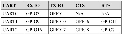
El IDF incluye un driver para las UART cuya API está definida en driver/uart.h. En arduino las UART están representadas
por los objetos SerialX, donde X corresponde a una UART especifica. Para configurar el objeto Serial en arduino se utiliza:
Serial.begin(speed) Serial.begin(speed, config)
Donde config permite definir la cantidad de bits, paridad, y el bit de parada. En el caso de IDF, una UART
se puede configurar definiendo la estructura de datos uart_config_t o también (como ocurrió con los GPIO)
llamando funciones particulares para configurar cada aspecto individualmente. Una vez populada la estructura, se le pasa a la
función uart_param_config(). Luego se mapea a los pines deseados con uart_set_pin() y finalmente se inicializa el
driver con uart_driver_install(). El siguiente codigo ilustra los pasos anteriores:
1 2 3 4 5 6 7 8 9 10 11 12 13 14 15 16 17 18 19 20 21 22 23 24 25 26 27 28 29 30 31 32 33 34 35 36 37 38 39 40 41 42 43 44 45 46 47 48 49 50 51 52 53 54 55 56 57 58 59 60 61 62 63 64 65 66 67 68 69 70 71 72 73 74 75 | /* UART asynchronous example, that uses separate RX and TX tasks
This example code is in the Public Domain (or CC0 licensed, at your option.)
Unless required by applicable law or agreed to in writing, this
software is distributed on an "AS IS" BASIS, WITHOUT WARRANTIES OR
CONDITIONS OF ANY KIND, either express or implied.
*/
#include "freertos/FreeRTOS.h"
#include "freertos/task.h"
#include "esp_system.h"
#include "esp_log.h"
#include "driver/uart.h"
#include "soc/uart_struct.h"
#include "string.h"
static const int RX_BUF_SIZE = 1024;
#define TXD_PIN (GPIO_NUM_4)
#define RXD_PIN (GPIO_NUM_5)
void init() {
const uart_config_t uart_config = {
.baud_rate = 115200,
.data_bits = UART_DATA_8_BITS,
.parity = UART_PARITY_DISABLE,
.stop_bits = UART_STOP_BITS_1,
.flow_ctrl = UART_HW_FLOWCTRL_DISABLE
};
uart_param_config(UART_NUM_1, &uart_config);
uart_set_pin(UART_NUM_1, TXD_PIN, RXD_PIN, UART_PIN_NO_CHANGE, UART_PIN_NO_CHANGE);
// We won't use a buffer for sending data.
uart_driver_install(UART_NUM_1, RX_BUF_SIZE * 2, 0, 0, NULL, 0);
}
int sendData(const char* logName, const char* data)
{
const int len = strlen(data);
const int txBytes = uart_write_bytes(UART_NUM_1, data, len);
ESP_LOGI(logName, "Wrote %d bytes", txBytes);
return txBytes;
}
static void tx_task()
{
static const char *TX_TASK_TAG = "TX_TASK";
esp_log_level_set(TX_TASK_TAG, ESP_LOG_INFO);
while (1) {
sendData(TX_TASK_TAG, "Hello world");
vTaskDelay(2000 / portTICK_PERIOD_MS);
}
}
static void rx_task()
{
static const char *RX_TASK_TAG = "RX_TASK";
esp_log_level_set(RX_TASK_TAG, ESP_LOG_INFO);
uint8_t* data = (uint8_t*) malloc(RX_BUF_SIZE+1);
while (1) {
const int rxBytes = uart_read_bytes(UART_NUM_1, data, RX_BUF_SIZE, 1000 / portTICK_RATE_MS);
if (rxBytes > 0) {
data[rxBytes] = 0;
ESP_LOGI(RX_TASK_TAG, "Read %d bytes: '%s'", rxBytes, data);
ESP_LOG_BUFFER_HEXDUMP(RX_TASK_TAG, data, rxBytes, ESP_LOG_INFO);
}
}
free(data);
}
void app_main()
{
init();
xTaskCreate(rx_task, "uart_rx_task", 1024*2, NULL, configMAX_PRIORITIES, NULL);
xTaskCreate(tx_task, "uart_tx_task", 1024*2, NULL, configMAX_PRIORITIES-1, NULL);
}
|
El código anterior está lleno de cosas interesantes (muchas preguntas de Juanito); sin embargo, antes de analizarlas, veamos algunos aspecetos interesantes del driver serial de IDF:
Al igual que el framework de Arduino, IDF utiliza buffers tipo
FIFOdonde se colocarán los datos que serán transmitidos o recibidos. Por tanto, y como en el caso de Arduino (Serial.read(),Serial.println()), las funciones del API de IDF están limitadas a leer o escribir de dichos buffers con uart_read_bytes() y uart_write_bytes().La función uart_read_bytes() es bloqueante; sin embargo, así como en el framework de Arduino (Serial.available()), es posible preguntar si hay datos disponibles en el buffer de recepción con uart_get_buffered_data_len():
// Read data from UART.
const int uart_num = UART_NUM_2;
uint8_t data[128];
int length = 0;
ESP_ERROR_CHECK(uart_get_buffered_data_len(uart_num, (size_t*)&length));
length = uart_read_bytes(uart_num, data, length, 100);
En caso de necesitar descartar todos los datos en el buffer de recepción se debe llamar
uart_flush().
Ahora sí, analicemos varios aspectos del ejercicio:
En la función
uart_driver_installel tamaño del buffer de transmisión se definió a cero indicando que el driver no utilizará un buffer de transmisión y por tanto las funciones de transmisión se bloquearán hasta que todos los datos hayan sido transmitidos.uart_driver_install permite informar, en una cola, los eventos que ocurren en el driver serial. En este enlace se puede ver un ejemplo que ilustra cómo funciona.
Las tareas de recepción y transmisión utilizan la función
void esp_log_level_set(const char *tag, esp_log_level_t level). La función recibe una cadena para identficar el módulo y un nivel de verbosidad. La función hace parte de la bilbioteca Logging de IDF. Unloges un registro que permite grabar acontecimientos en el sistema. En este caso los logs son enviados a la UART0.esp_log_level_set()permite disminuir en tiempo de ejecución el nivel de verbosidad de los logs de cada módulo; sin embargo, el nivel de verbosidad máximo se configura en tiempo de compilación conCONFIG_LOG_DEFAULT_LEVELenmenuconfig. Un módulo puede ser un archivo o una tarea. Se identifica por una etiqueta o TAG. El nivel de verbosidad de menor nivel a mayor es:Error,Warning,Info,DebugyVerbose. El nivel por defecto deCONFIG_LOG_DEFAULT_LEVELesInfo. IDF permite aumentar por archivo el nivel de verbosidad definiendo en ese archivo el macro LOG_LOCAL_LEVEL así:#define LOG_LOCAL_LEVEL ESP_LOG_VERBOSE #include "esp_log.h"
Para usar la biblioteca
Loggingse debe definir en cada archivo o tarea una etiqueta y luego se utiliza un logging macro:static const char *TX_TASK_TAG = "TX_TASK"; o static const char *RX_TASK_TAG = "RX_TASK"; ESP_LOGE - error (lowest) ESP_LOGW - warning ESP_LOGI - info ESP_LOGD - debug ESP_LOGV - verbose (highest)
En el ejercicio:
ESP_LOGI(logName, "Wrote %d bytes", txBytes);
En el ejercicio también se usa
ESP_LOG_BUFFER_HEXDUMP(tag, buffer, buff_len, level). Este macro volca un buffer a un determinado nivel de verbosidad. Por ejemplo:W (195) log_example: 0x3ffb4280 45 53 50 33 32 20 69 73 20 67 72 65 61 74 2c 20 |ESP32 is great, | W (195) log_example: 0x3ffb4290 77 6f 72 6b 69 6e 67 20 61 6c 6f 6e 67 20 77 69 |working along wi| W (205) log_example: 0x3ffb42a0 74 68 20 74 68 65 20 49 44 46 2e 00 |th the IDF..|
Finalmente,
rx_taskutiliza memoria dinámica, es decir, memoria que se maneja en elheapo zona de memoria dinámica. El manejo de memoria dinámica en C se hace manualmente, a diferencia de python, java o C# que cuentan con mecanismos automáticos de manejo de memoria conocidos comogarbage collectors. Por tanto, la memoria se reserva conmallocy luego debe liberarse manualmente confree(). En el ejercicio,mallocrecibe la cantidad de bytes a reservar y devuelvo un puntero genérico,void *.freerecibe el puntero devuelto por malloc.
Ejercicio 4: otros periféricos
El ESP32 es rico en periféricos. El propósito de este ejercicio es explorar libremente algunos de ellos:
- El equivalente en Arduino a
analogRead(): ADC. - El equivalente en Arduino a
analogWrite()cuando el microcontrolador posee realmente convertidor digital a análogo: DAC. - El equivalente en Arduino a
analogWrite()cuando la salida esPWM: LED control module.
La última estación del recorrido: Active Object
En este punto del recorrido hemos visitado diferentes maneras de desarrollar aplicaciones para sistemas embebidos.
Desde la arquetectura background/foreground clásica, utilizada por Arduino, pasando por las máquinas de estado jerárquicas,
hasta los sistemas operativos de tiempo real ilustrados con FreeRTOS. Ahora nos dirigiremos a la última estación
de este recorridos. Se trata del patrón de diseño Active Objects u Objetos Activos.
Patrón de diseño de Objetos Activos
El material que se presentará a continuación está basado en:
- Los conceptos claves de programación de sistemas embebidos tratados aquí.
- En esta presentación de Miro Samek.
- En uno de los capítulos del texto
Practical UML statecharts in C/C++de Miro Samek. - Curso corto sobre máquinas de estado en UML.
- Material del curso controladores: semana11 clase 1 y clase 2.
¿Para qué sirve el patrón Objetos Activos ?
Este patrón de diseño sirve para la construcción de software de sistemas de naturaleza reactiva. Los sistemas reactivos se
caracterizan por reaccionar ante la ocurrencia de eventos. Por ejemplo, la llegada de un mensaje
por un puerto de comunicaciones, la disponibilidad de un dato por parte de un sensor, timeouts, una petición HTTP por
parte de un cliente a un servidor, etc. El software para un sistema reactivo responde a la ocurrencia de eventos que no
tienen necesariamente un orden establecido. En contraste, el software construido con programación secuencial espera de
manera secuencial por la ocurrencia de un evento específico, haciendo que, mientras espera, no responda a otros eventos.
Por ejemplo:
// the setup function runs once when you press reset or power the board
void setup() {
// initialize digital pin LED_BUILTIN as an output.
pinMode(LED_BUILTIN, OUTPUT);
}

// the loop function runs over and over again forever
void loop() {
digitalWrite(LED_BUILTIN, HIGH);   // turn the LED on (HIGH is the voltage level)
delay(1000);                       // wait for a second
digitalWrite(LED_BUILTIN, LOW);    // turn the LED off by making the voltage LOW
delay(1000);                       // wait for a second
}
En este código de Arduino, mientras se espera por el evento de tiempo (delay(1000)), el programa del usuario no respondará
a otros eventos, por ejemplo, la llegada de un nuevo dato por el puerto serial.
Durante estas semanas hemos visto que un sistema operativo de tiempo real permite enfrentar el problema anterior utilizando
múltiples loops (tareas) corriendo concurrentemente en la misma CPU o de manera paralela en múltiples CPUs. De esta manera,
es posible esperar por múltiples eventos en paralelo. Por ejemplo, una tarea para esperar una dato por el puerto serial y otra
para encender y apagar un LED. Dice Juanito: a mi me parece todo muy bonito. Sin embargo, los problemas comienzan cuando
las tareas deben sincronizarse y comunicarse entre ellas. Esto produce una suerte de estado compartido y la necesidad de aplicar
mecanismos de exclusión mutua para evitar condiciones de carrera. Como hemos visto durante el curso, un RTOS provee mecanismos,
mediante llamadas bloqueantes al sistema, tales como las colas de eventos y los semáforos para lidiar con lo anterior;
sin embargo, aparecen nuevos problemas como la inanición de tareas o thread starvation, abrazos mortales o deadlocks e inversión de prioridad o
priority inversion.
Debido a lo anterior, actualemente muchos expertos recomiendan mejores prácticas de desarrollo para sistemas reactivos:
- No hacer llamados bloqueantes en el código. Más bien comunicar las tareas de manera asincrónica por medio de eventos.
- No compartir datos o recursos entre tareas. Mantener los recursos
encapsuladosen cada tareas y mejor utilizar eventos para compartir información. - Organizar las tareas como “bombas de mensajes”: con una cola de eventos y un depachador de eventos.
Al uso de estas prácticas se le conoce como programación guiada por eventos. La siguiente figura, tomada de la presentación
Modern Embedded Systems Programming: Beyond the RTOS de Miro Samek, ilustra cómo se podrían implementar las ideas anteriores
utilizando un sistema operativo de tiempo real:
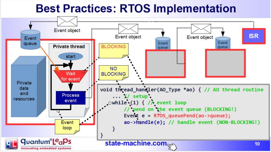
- Se define un evento (un objeto o estructura de datos) que indica el evento específico y sus parámetros.
- Cada tarea tendrá su propia cola de mensajes que almacenará los eventos anteriores.
- Las tareas
SÓLOse comunicarán y sincronizarán por medio de eventos enviados a sus colas. No está permitido que las tareas compartan datos o recursos. - El envio de mensajes es asincrónico, es decir, ninguna tarea puede esperar (espera bloqueada) por el procesamiento del evento.
- El código de la tarea se organiza como una “bomba de eventos”. La tarea sólo se bloquea cuando su cola está vacía, no en otra parte del código.
- Cada evento es procesado antes de procesar el siguiente:
run to completion.
¿Qué es el patrón diseño ACTIVE OBJECT?
A todas las buenas prácticas anteriores y a la estrategia de implementación se le conoce como el patrón de Objetos Activos o patrón del Actor. Los objetos activos son objetos de software estrictamente encapsulados que corren sobre sus propios hilos (tarea) y se comunican de manerá asincrónica utilizando eventos.
Esta idea la propuso en los 70s Carl Hewitt en MIT. En los años 90s la metodología ROOM para el modelado de sistemas de tiempo real retomó la idea y posteriormente UML introdujo la noción de objetos activos. Tanto los objetos activos de ROOM como los de UML emplean máquinas de estado jerárquicas para especificar el comportamiento de dichos objetos.
En este curso vamos a implementar el patrón de objetos activos manualmente utilizando FreeRTOS; sin embargo, es posible utilizar
frameworks como QP de quantum leaps:
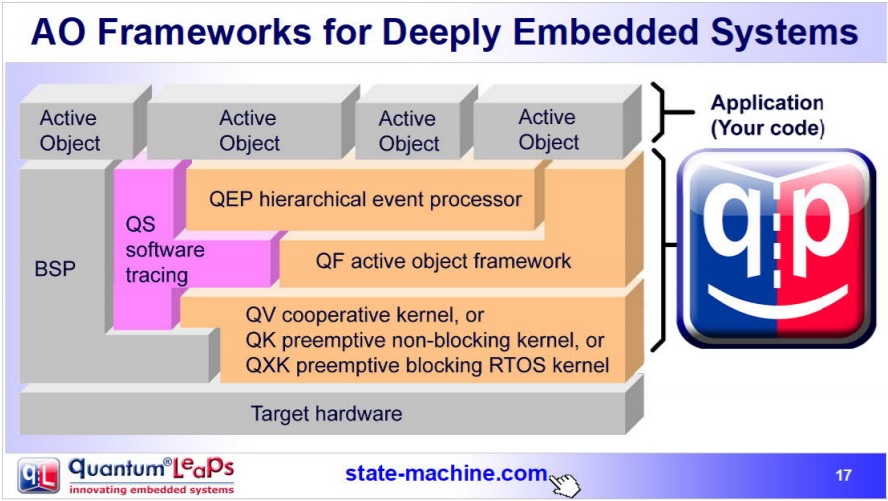
Pregunta Junito: ¿Qué son las máquinas de estado jerárquicas? En este punto se recomienda repasar el material del curso de controladores relacionado: semana11 clase 1 y clase 2.
Ejercicio: reto
Utilizando el patrón de objeto activo implemente un programa que controle de manera independiente tres LEDs. El control de cada LED se realiza mediante comandos que serán enviados por un puerto serial de aplicación del ESP32, es decir, debe utilizar un puerto serial diferente al puerto de depuración. Los comandos para cada LED son: encendido, apagado, programación de pulso (programar tiempo de activación y tiempo de encendido) y encendido apagado periódico. Antes de comenzar a programar, realice un modelo del sistema utilizando objetos activos y máquinas de estados jerárquicas para especificar el comportamiento de cada objeto. Considere el material de la semana 4 para repasar los conceptos de comunicación entre tareas y la creación de eventos, ejercicio 3.
Material de referencia para el reto
En base a este ejemplo (tomado del proyecto SinelaboreRT), vamos a ilustrar la implementación, mediante un objeto activo, de la tarea que controla el LED:
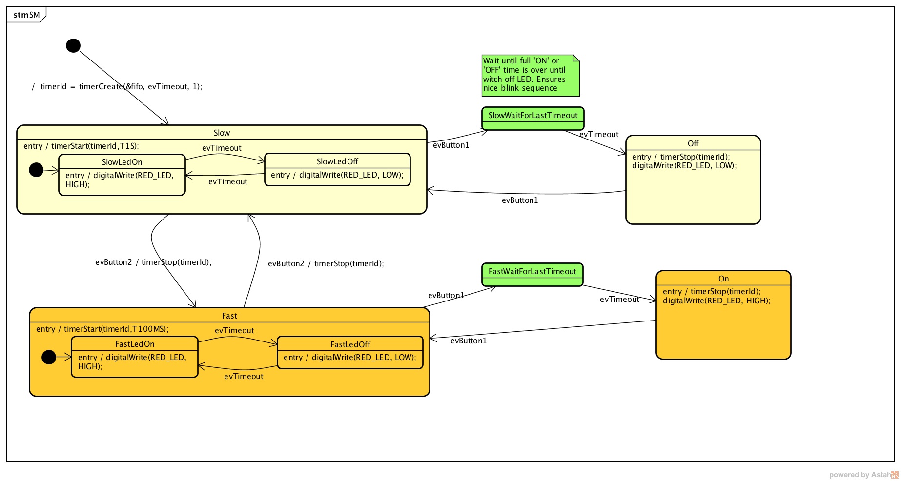
1 2 3 4 5 6 7 8 9 10 11 12 13 14 15 16 17 18 19 20 21 22 23 24 25 26 27 28 29 30 31 32 33 34 35 36 37 38 39 40 41 42 43 44 45 46 47 48 49 50 51 52 53 54 55 56 57 58 59 60 61 62 63 64 65 66 67 68 69 70 71 72 73 74 75 76 77 78 79 80 81 82 83 84 85 86 87 88 89 90 91 92 93 94 95 96 97 98 99 100 101 102 103 104 105 106 107 108 109 110 111 112 113 114 115 116 117 118 119 120 121 122 123 124 125 126 127 128 129 130 131 132 133 134 135 136 137 138 139 140 141 142 143 144 145 146 147 148 149 150 151 152 153 154 155 156 157 158 159 160 161 162 163 164 165 166 167 168 169 170 171 172 173 174 175 176 177 178 179 180 181 182 183 184 185 186 187 188 189 190 191 192 193 194 195 196 197 198 199 200 201 202 203 204 205 206 207 208 209 210 211 212 213 214 215 216 217 218 219 220 221 222 223 224 225 226 227 228 229 230 231 232 233 234 235 236 237 238 239 240 241 242 243 244 245 246 247 248 249 250 251 252 253 254 255 256 257 258 259 260 261 262 263 264 265 266 267 268 269 270 271 272 273 274 275 276 277 278 279 280 281 282 283 284 285 286 287 288 289 290 291 292 293 294 295 296 297 298 299 300 301 302 303 304 305 306 307 308 309 310 311 312 313 314 315 316 317 318 319 320 321 322 323 324 325 326 327 328 329 330 331 332 333 334 335 336 337 338 339 340 341 342 343 344 345 346 347 348 349 350 351 352 353 354 355 356 357 358 359 360 361 362 363 364 365 366 367 368 369 370 371 372 373 374 375 376 377 378 379 380 381 382 383 384 385 386 387 388 389 390 391 392 393 394 395 396 397 398 399 400 401 402 403 404 405 406 407 408 409 410 411 412 413 414 415 416 417 418 419 420 421 422 423 424 425 426 427 428 429 430 431 432 433 434 435 436 437 438 439 440 441 442 443 444 445 446 447 448 449 450 451 452 | #include "freertos/FreeRTOS.h"
#include "freertos/task.h"
#include "esp_system.h"
#include "esp_log.h"
#include "driver/uart.h"
#include "soc/uart_struct.h"
#include "string.h"
#include "freertos/queue.h"
#include "freertos/timers.h"
static const int RX_BUF_SIZE = 1024;
#define TXD_PIN (GPIO_NUM_4)
#define RXD_PIN (GPIO_NUM_5)
#define GPIO_OUTPUT_IO_0 GPIO_NUM_18
typedef enum{
evTimeout = 0U,
evButton2,
evButton1,
AOBLINK_NO_MSG
}AOBLINK_EVENT_TYPE;
/* Event names */
const char events[] =
"evTimeout\0evButton2\0evButton1\0NO_MSG\0";
const unsigned short evt_idx[] = {0, 10, 20, 30};
QueueHandle_t aoBlinkQueue;
typedef struct
{
AOBLINK_EVENT_TYPE evType;
uint8_t evData;
} evAoBlink;
TimerHandle_t aoTimer;
const char *getNameByEvent(AOBLINK_EVENT_TYPE evt)
{
return (events + evt_idx[evt]);
}
void init()
{
const uart_config_t uart_config = {
.baud_rate = 115200,
.data_bits = UART_DATA_8_BITS,
.parity = UART_PARITY_DISABLE,
.stop_bits = UART_STOP_BITS_1,
.flow_ctrl = UART_HW_FLOWCTRL_DISABLE};
uart_param_config(UART_NUM_1, &uart_config);
uart_set_pin(UART_NUM_1, TXD_PIN, RXD_PIN, UART_PIN_NO_CHANGE, UART_PIN_NO_CHANGE);
// We won't use a buffer for sending data.
uart_driver_install(UART_NUM_1, RX_BUF_SIZE * 2, 0, 0, NULL, 0);
// Configure Output
gpio_intr_disable(GPIO_OUTPUT_IO_0);
gpio_set_level(GPIO_OUTPUT_IO_0, 0);
gpio_pullup_dis(GPIO_OUTPUT_IO_0);
gpio_pulldown_dis(GPIO_OUTPUT_IO_0);
gpio_set_direction(GPIO_OUTPUT_IO_0, GPIO_MODE_OUTPUT);
}
static void aoTimerCallback(TimerHandle_t xTimer)
{
BaseType_t xStatus;
evAoBlink ev;
//printf("Sending timerEvent\r\n");
ev.evType = evTimeout;
ev.evData = 0;
xStatus = xQueueSendToBack(aoBlinkQueue, &ev, 0);
if (xStatus != pdPASS)
{
printf("aoTimerCallback couldn't send\r\n");
}
}
typedef enum
{
Fast,
FastLedOn,
FastLedOff,
Off,
On,
SlowWaitForLastTimeout,
FastWaitForLastTimeout,
Slow,
SlowLedOn,
SlowLedOff,
NUM_STATES // number of states in the machine
} States;
int m_initialized;
typedef struct
{
States stateVar;
States stateVarSlow;
States stateVarFast;
} stateVarsT;
stateVarsT stateVars;
stateVarsT stateVarsCopy;
static void initStateMachine(void)
{
BaseType_t xTimerCreatedStatus;
if (m_initialized == 0U)
{
m_initialized = 1U;
//Create copy of statevar
stateVarsCopy = stateVars;
// Set state vars to default states
stateVarsCopy.stateVar = Slow; /* set init state of top state */
stateVarsCopy.stateVarSlow = SlowLedOn; /* set init state of Slow */
stateVarsCopy.stateVarFast = FastLedOn; /* set init state of Fast */
aoTimer = xTimerCreate("aoTimer", pdMS_TO_TICKS(1000UL), pdTRUE, NULL, aoTimerCallback);
if (aoTimer != NULL)
{
printf("aoTimer created\r\n");
xTimerCreatedStatus = xTimerStart(aoTimer, 0);
if (xTimerCreatedStatus == pdPASS)
{
printf("aoTimer started\r\n");
}
}
gpio_set_level(GPIO_OUTPUT_IO_0, pdTRUE);
printf("LED OFF \r\n");
// Copy state variables back
stateVars = stateVarsCopy;
}
}
static void aoStateMachine(evAoBlink event)
{
int evConsumed = 0U;
if (m_initialized == 0U)
return;
//Create copy of statevar
stateVarsCopy = stateVars;
switch (stateVars.stateVar)
{
case Slow:
switch (stateVars.stateVarSlow)
{
case SlowLedOn:
if (event.evType == evTimeout)
{
/* Transition from SlowLedOn to SlowLedOff */
evConsumed = 1;
/* OnEntry code of state SlowLedOff */
gpio_set_level(GPIO_OUTPUT_IO_0, pdFALSE);
printf("LED OFF\r\n");
/* adjust state variables */
stateVarsCopy.stateVarSlow = SlowLedOff;
}
else
{
/* Intentionally left blank */
} /*end of event selection */
break; /* end of case SlowLedOn */
case SlowLedOff:
if (event.evType == evTimeout)
{
/* Transition from SlowLedOff to SlowLedOn */
evConsumed = 1;
/* OnEntry code of state SlowLedOn */
gpio_set_level(GPIO_OUTPUT_IO_0, pdTRUE);
printf("LED ON\r\n");
/* adjust state variables */
stateVarsCopy.stateVarSlow = SlowLedOn;
}
else
{
/* Intentionally left blank */
} /*end of event selection */
break; /* end of case SlowLedOff */
default:
/* Intentionally left blank */
break;
} /* end switch Slow */
/* Check if event was already processed */
if (evConsumed == 0)
{
if (event.evType == evButton1)
{
/* Transition from Slow to SlowWaitForLastTimeout */
evConsumed = 1;
/* adjust state variables */
stateVarsCopy.stateVar = SlowWaitForLastTimeout;
}
else if (event.evType == evButton2)
{
/* Transition from Slow to Fast */
evConsumed = 1;
/* Action code for transition */
xTimerChangePeriod(aoTimer,pdMS_TO_TICKS(100UL),0);
gpio_set_level(GPIO_OUTPUT_IO_0, pdTRUE);
printf("LED ON\r\n");
stateVarsCopy.stateVar = Fast; /* Default in entry chain */
stateVarsCopy.stateVarFast = FastLedOn; /* Default in entry chain */
}
else
{
/* Intentionally left blank */
} /*end of event selection */
}
break; /* end of case Slow */
case Fast:
switch (stateVars.stateVarFast)
{
case FastLedOn:
if (event.evType == evTimeout)
{
/* Transition from FastLedOn to FastLedOff */
evConsumed = 1;
/* OnEntry code of state FastLedOff */
gpio_set_level(GPIO_OUTPUT_IO_0, pdFALSE);
printf("LED OFF\r\n");
/* adjust state variables */
stateVarsCopy.stateVarFast = FastLedOff;
}
else
{
/* Intentionally left blank */
} /*end of event selection */
break; /* end of case FastLedOn */
case FastLedOff:
if (event.evType == evTimeout)
{
/* Transition from FastLedOff to FastLedOn */
evConsumed = 1;
/* OnEntry code of state FastLedOn */
gpio_set_level(GPIO_OUTPUT_IO_0, pdTRUE);
printf("LED ON\r\n");
/* adjust state variables */
stateVarsCopy.stateVarFast = FastLedOn;
}
else
{
/* Intentionally left blank */
} /*end of event selection */
break; /* end of case FastLedOff */
default:
/* Intentionally left blank */
break;
} /* end switch Fast */
/* Check if event was already processed */
if (evConsumed == 0)
{
if (event.evType == evButton1)
{
/* Transition from Fast to FastWaitForLastTimeout */
evConsumed = 1;
/* adjust state variables */
stateVarsCopy.stateVar = FastWaitForLastTimeout;
}
else if (event.evType == evButton2)
{
/* Transition from Fast to Slow */
evConsumed = 1;
/* Action code for transition */
xTimerChangePeriod(aoTimer,pdMS_TO_TICKS(1000UL),0);
gpio_set_level(GPIO_OUTPUT_IO_0, pdTRUE);
printf("LED ON\r\n");
stateVarsCopy.stateVar = Slow; /* Default in entry chain */
stateVarsCopy.stateVarSlow = SlowLedOn; /* Default in entry chain */
}
else
{
/* Intentionally left blank */
} /*end of event selection */
}
break; /* end of case Fast */
case Off:
if (event.evType == evButton1)
{
/* Transition from Off to Slow */
evConsumed = 1;
/* OnEntry code of state Slow */
xTimerChangePeriod(aoTimer,pdMS_TO_TICKS(1000UL),0);
gpio_set_level(GPIO_OUTPUT_IO_0, pdTRUE);
printf("LED ON\r\n");
stateVarsCopy.stateVar = Slow; /* Default in entry chain */
stateVarsCopy.stateVarSlow = SlowLedOn; /* Default in entry chain */
}
else
{
/* Intentionally left blank */
} /*end of event selection */
break; /* end of case Off */
case On:
if (event.evType == evButton1)
{
/* Transition from On to Fast */
evConsumed = 1;
/* OnEntry code of state Fast */
xTimerChangePeriod(aoTimer,pdMS_TO_TICKS(100UL),0);
gpio_set_level(GPIO_OUTPUT_IO_0, pdTRUE);
printf("LED ON\r\n");
stateVarsCopy.stateVar = Fast; /* Default in entry chain */
stateVarsCopy.stateVarFast = FastLedOn; /* Default in entry chain */
}
else
{
/* Intentionally left blank */
} /*end of event selection */
break; /* end of case On */
case SlowWaitForLastTimeout:
if (event.evType == evTimeout)
{
/* Transition from SlowWaitForLastTimeout to Off */
evConsumed = 1;
/* OnEntry code of state Off */
xTimerStop(aoTimer,0);
gpio_set_level(GPIO_OUTPUT_IO_0, pdFALSE);
printf("LED OFF\r\n");
/* adjust state variables */
stateVarsCopy.stateVar = Off;
}
else
{
/* Intentionally left blank */
} /*end of event selection */
break; /* end of case SlowWaitForLastTimeout */
case FastWaitForLastTimeout:
if (event.evType == evTimeout)
{
/* Transition from FastWaitForLastTimeout to On */
evConsumed = 1;
/* OnEntry code of state On */
xTimerStop(aoTimer,0);
gpio_set_level(GPIO_OUTPUT_IO_0, pdTRUE);
printf("LED ON\r\n");
/* adjust state variables */
stateVarsCopy.stateVar = On;
}
else
{
/* Intentionally left blank */
} /*end of event selection */
break; /* end of case FastWaitForLastTimeout */
default:
/* Intentionally left blank */
break;
} /* end switch stateVar_root */
// Copy state variables back
stateVars = stateVarsCopy;
}
static void aoBlink(void *pdata)
{
BaseType_t xStatus;
evAoBlink rxEvent;
initStateMachine();
while (1)
{
xStatus = xQueueReceive(aoBlinkQueue, &rxEvent, portMAX_DELAY);
if (xStatus == pdPASS)
{
printf("EV_type:%s-Data: %d\r\n", getNameByEvent(rxEvent.evType), rxEvent.evData);
aoStateMachine(rxEvent);
}
}
}
static void serialTask(void *pdata)
{
evAoBlink ev;
BaseType_t xStatus;
uint8_t data[2];
printf("serialTask init\r\n");
while (1)
{
const uint8_t rxBytes = uart_read_bytes(UART_NUM_1, data, 1, 1000 / portTICK_RATE_MS);
if (rxBytes > 0)
{
data[rxBytes] = 0;
printf("Read: %s\r\n", data);
ev.evType = AOBLINK_NO_MSG;
if (data[0] == '1')
ev.evType = evButton1;
if (data[0] == '2')
ev.evType = evButton2;
ev.evData = 0;
xStatus = xQueueSendToBack(aoBlinkQueue, &ev, 0);
if (xStatus != pdPASS)
{
printf("Could not send to the queue.\r\n");
}
}
}
}
void app_main()
{
init();
aoBlinkQueue = xQueueCreate(10, sizeof(evAoBlink));
if (aoBlinkQueue != NULL)
{
printf("aoBlink state machine created\r\n");
xTaskCreate(aoBlink, "aoBlink", 1024 * 2, NULL, configMAX_PRIORITIES, NULL);
xTaskCreate(serialTask, "serialTask", 1024 * 2, NULL, configMAX_PRIORITIES - 1, NULL);
}
else
{
printf("aoBlinkQueue is not created\r\n");
}
}
|