Unidad 3. Sensores y actuadores inalámbricos
Introducción
En esta unidad vamos a estudiar cómo conectar sensores y actuadores a una aplicación mediante protocolos de comunicación inalámbricos en una red WiFi.
Propósito de aprendizaje
Crear aplicaciones interactivas de tiempo real que integren sensores y actuadores mediante protocolos de comunicación inalámbrica.
Temas
- WiFi
- TCP
- UDP
Trayecto de actividades
Ejercicio 1
Con este ejercicio aprenderás a conectar un sensor/actuador a una red WiFi y a comunicar esos dispositivos mediante el protocolo TCP.
Inicia trabajando con esta guía.
Ejercicio 2
Ahora vamos a explorar UDP mediante el análisis de un proyecto simple que ilustra el uso del protocolo.
Se trata de un conjunto de actuadores distribuidos en el espacio y un coordinar central, un PC. Cada actuador enciende y apaga un puerto de entrada salida según lo indique el comando que recibido por UDP. Dicho comando será enviado por el coordinador central. El coordinador cuenta con un dispositivo, que llamaremos bridge, quien recibirá por serial los comandos y los reenvía por UDP a los actuadores distribuidos.
El protocolo de comunicación serial es simple. Se trata de un protocolo ascii compuesto por tres caracteres. El primer carácter indica a cual actuador se enviará el comando. El segundo carácter el estado deseado para la salida (‘1’ on, ‘0’ off). Por último, se envía un carácter de sincronización (‘*’).
El código del bridge (el que recibe los comandos por serial y envía por WiFi) es el siguiente:
1 2 3 4 5 6 7 8 9 10 11 12 13 14 15 16 17 18 19 20 21 22 23 24 25 26 27 28 29 30 31 32 33 34 35 36 37 38 39 40 41 42 43 44 45 46 47 48 49 50 51 52 53 54 55 56 57 58 59 60 61 62 63 64 65 66 67 68 69 70 71 72 73 74 75 76 77 78 79 80 81 82 83 84 85 86 87 88 89 90 91 92 93 | #include <WiFi.h>
#include <WiFiUdp.h>
const char* ssid = "?";
const char* password = "?";
WiFiUDP udpDevice;
uint16_t localUdpPort = ?;
uint16_t UDPPort = ?;
#define MAX_LEDSERVERS 3
const char* hosts[MAX_LEDSERVERS] = {"?.?.?.?", "?.?.?.?", "?.?.?.?"};
#define SERIALMESSAGESIZE 3
uint32_t previousMillis = 0;
#define ALIVE 1000
#define D0 5
void setup() {
pinMode(D0, OUTPUT); // Initialize the LED_BUILTIN pin as an output
digitalWrite(D0, HIGH);
Serial.begin(115200);
Serial.println();
Serial.println();
Serial.print("Connecting to ");
Serial.println(ssid);
WiFi.mode(WIFI_STA);
WiFi.begin(ssid, password);
while (WiFi.status() != WL_CONNECTED) {
delay(500);
Serial.print(".");
}
Serial.println("");
Serial.println("WiFi connected");
// Print the IP address
Serial.println(WiFi.localIP());
udpDevice.begin(localUdpPort);
}
void networkTask() {
uint8_t LEDServer = 0;
uint8_t LEDValue = 0;
uint8_t syncChar;
// Serial event:
if (Serial.available() >= SERIALMESSAGESIZE) {
LEDServer = Serial.read() - '0';
LEDValue = Serial.read();
syncChar = Serial.read();
if ((LEDServer == 0) || (LEDServer > 3)) {
Serial.println("Servidor inválido (seleccione 1,2,3)");
return;
}
if (syncChar == '*') {
udpDevice.beginPacket(hosts[LEDServer - 1] , UDPPort);
udpDevice.write(LEDValue);
udpDevice.endPacket();
}
}
// UDP event:
uint8_t packetSize = udpDevice.parsePacket();
if (packetSize) {
Serial.print("Data from: ");
Serial.print(udpDevice.remoteIP());
Serial.print(":");
Serial.print(udpDevice.remotePort());
Serial.print(' ');
for (uint8_t i = 0; i < packetSize; i++) {
Serial.write(udpDevice.read());
}
}
}
void aliveTask() {
uint32_t currentMillis;
static uint8_t ledState = 0;
currentMillis = millis();
if ((currentMillis - previousMillis) >= ALIVE) {
previousMillis = currentMillis;
if (ledState == 0) {
digitalWrite(D0, HIGH);
ledState = 1;
}
else {
digitalWrite(D0, LOW);
ledState = 0;
}
}
}
void loop() {
networkTask();
aliveTask();
}
|
Nota que a diferencia de TCP/IP, con UDP no es necesario establecer una conexión. Los pasos necesario para enviar datos por UDP serán:
- Crear un objeto WiFiUDP
- Iniciar el objeto estableciendo un socket compuesto por la dirección IP y el puerto de escucha.
- Iniciar la construcción del paquete a transmitir con beginPacket(),
- Popular el buffer de transmisión con write.
- Enviar el paquete con endPacket().
El código de los actuadores distribuidos será:
1 2 3 4 5 6 7 8 9 10 11 12 13 14 15 16 17 18 19 20 21 22 23 24 25 26 27 28 29 30 31 32 33 34 35 36 37 38 39 40 41 42 43 44 45 46 47 48 49 50 51 52 53 54 55 56 57 58 59 60 61 62 63 64 65 66 67 68 69 70 | #include <WiFi.h>
#include <WiFiUdp.h>
const char* ssid = "?";
const char* password = "?";
WiFiUDP udpDevice;
uint16_t localUdpPort = ?;
uint32_t previousMillis = 0;
#define ALIVE 1000
#define D0 5
#define D8 18
void setup() {
pinMode(D0, OUTPUT); // Initialize the LED_BUILTIN pin as an output
digitalWrite(D0, HIGH);
pinMode(D8, OUTPUT);
digitalWrite(D8, LOW);
Serial.begin(115200);
Serial.println();
Serial.println();
Serial.print("Connecting to ");
Serial.println(ssid);
WiFi.mode(WIFI_STA);
WiFi.begin(ssid, password);
while (WiFi.status() != WL_CONNECTED) {
delay(500);
Serial.print(".");
}
Serial.println("");
Serial.println("WiFi connected");
// Print the IP address
Serial.println(WiFi.localIP());
udpDevice.begin(localUdpPort);
}
void networkTask() {
uint8_t data;
uint8_t packetSize = udpDevice.parsePacket();
if (packetSize) {
data = udpDevice.read();
if (data == '1') {
digitalWrite(D0, HIGH);
} else if (data == '0') {
digitalWrite(D0, LOW);
}
// send back a reply, to the IP address and port we got the packet from
udpDevice.beginPacket(udpDevice.remoteIP(), udpDevice.remotePort());
udpDevice.write('1');
udpDevice .endPacket();
}
}
void aliveTask() {
uint32_t currentMillis;
static uint8_t ledState = 0;
currentMillis = millis();
if ((currentMillis - previousMillis) >= ALIVE) {
previousMillis = currentMillis;
if (ledState == 0) digitalWrite(D8, HIGH);
else digitalWrite(D8, LOW);
}
}
void loop() {
networkTask();
aliveTask();
}
|
Los pasos para recibir datos por UDP son:
- Crear un objeto WiFiUDP
- Iniciar el objeto estableciendo un socket compuesto por la dirección IP y el puerto de escucha.
- Procesar el siguiente paquete UDP con parsePacket(). Esta acción devolverá el tamaño del paquete en bytes.
- Luego de llamar parsePacket() será posible utilizar los métodos read() y available().
- Leer el paquete.
En el ejemplo mostrado, nota que un actuador distribuido responderá al bridge con el carácter ‘1’ cada que reciba un paquete. De esta manera el bridge sabrá que el dato llegó a su destino.
Ejercicio 3: despliegue del ejercicio
Para desplegar este ejercicio necesitaras varios dispositivos: PC y dos ESP32. Puedes usar un ESP32 para implementar el bridge y otro para implementar un actuador. Así mismo puedes emplear el PC como coordinador y como uno o varios actuadores virtuales. También podrías emplear el celular para simular un actuador.
Para desplegar el ejercicio es necesario identificar claramente las direcciones IP de cada uno de los actuadores remotos.
Utiliza un ESP32 para cada actuador y un ESP32 para el bridge. Si no cuentas con todos los dispositivos, entonces puedes:
- Usar el ESP32 como bridge y como actuadores el celular y el computador.
- Utiliza los programas Hercules o ScriptCommunicator para simular la aplicación del PC y los actuadores.
Ejercicio 4: integración con Unity
Observa este video. Vamos a analizar cómo podríamos hacer para realizar una aplicación similar que utilice realidad virtual, pero que integre dispositivos físicos en un ambiente real.
La aplicación se desplegará en un cuarto cuadrado que modelaremos como muestra la figura:
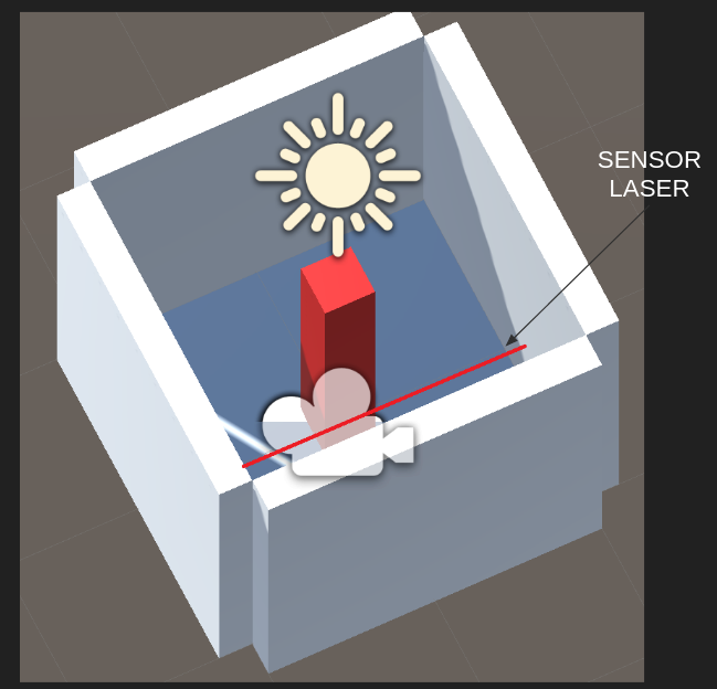
Recuerda, tenemos un espacio físico y su respectivo modelo virtual. Por tanto, si tocas las paredes virtuales, sentirás las mismas paredes en el mundo físico.
Nota que en el centro hay un tótem que cambiará de color si el usuario es detectado por un sensor laser.
El sensor laser y la aplicación VR están conectados por medio de una red WiFi utilizando sockets UDP.
Si el sensor láser se activa se enviará el mensaje: sensor 2 y el material del tótem
cambiará de rojo a negro. sensor 1 hará que el color vuelva a rojo.
Como el protocolo de comunicación es UDP, buscamos en la documentación de C#. Allí incluso encontramos un ejemplo:
1 2 3 4 5 6 7 8 9 10 11 12 13 14 15 16 17 18 19 20 21 22 23 | //Creates a UdpClient for reading incoming data.
UdpClient receivingUdpClient = new UdpClient(11000);
//Creates an IPEndPoint to record the IP Address and port number of the sender.
// The IPEndPoint will allow you to read datagrams sent from any source.
IPEndPoint RemoteIpEndPoint = new IPEndPoint(IPAddress.Any, 0);
try{
// Blocks until a message returns on this socket from a remote host.
Byte[] receiveBytes = receivingUdpClient.Receive(ref RemoteIpEndPoint);
string returnData = Encoding.ASCII.GetString(receiveBytes);
Console.WriteLine("This is the message you received " +
returnData.ToString());
Console.WriteLine("This message was sent from " +
RemoteIpEndPoint.Address.ToString() +
" on their port number " +
RemoteIpEndPoint.Port.ToString());
}
catch ( Exception e ){
Console.WriteLine(e.ToString());
}
|
Pero más abajo leemos:
The Receive method will block until a datagram arrives from a remote host. When data is available, the Receive method will read the first enqueued datagram and return the data portion as a byte array. This method populates the remoteEP parameter with the IPAddress and port number of the sender.
Como ya sabemos esto hace que tengamos que usar un HILO para realizar la comunicación, de lo contrario nuestra aplicación interactiva estaría bloqueada mientras se espera por la llegada de datos.
No hay problema. Ya sabemos cómo usar hilos cuando estudiamos Ardity. Este podría ser entonces el código de nuestro hilo:
1 2 3 4 5 6 7 8 9 10 11 12 13 14 15 16 | private void ReceiveDataListener()
{
while (true)
{
try
{
byte[] data = receiveClient.Receive(ref receiveEndPoint);
string text = Encoding.UTF8.GetString(data);
SerializeMessage(text);
}
catch (System.Exception ex)
{
Debug.Log(ex.ToString());
}
}
}
|
No olvides, que no podemos acceder la API de Unity desde un hilo diferente al GameLoop. ¿Entonces qué hacemos? Ya sabes: COLAS, como hicimos al estudiar Ardity.
1 2 3 4 5 6 7 8 9 10 11 12 13 14 15 16 17 | private void SerializeMessage(string message)
{
try
{
string[] chain = message.Split(' ');
string key = chain[0];
float value = 0;
if (float.TryParse(chain[1], out value))
{
receiveQueue.Enqueue(value);
}
}
catch (System.Exception e)
{
Debug.Log(e.ToString());
}
}
|
Y cómo quedaría entonces la aplicación:
1 2 3 4 5 6 7 8 9 10 11 | void Update()
{
if (receiveQueue.Count != 0)
{
float counter = (float)receiveQueue.Dequeue();
if(counter == 1F) m_Material.color = Color.black;
if(counter == 2F) m_Material.color = Color.red;
}
}
|
Ejercicio 5: RETO
Analiza con detenimiento el siguiente ejemplo. Te recomiendo que lo implementes utilizando un computador y un ESP32:
1 2 3 4 5 6 7 8 9 10 11 12 13 14 15 16 17 18 19 20 21 22 23 24 25 26 27 28 29 30 31 32 33 34 35 36 37 38 39 40 41 42 43 44 45 46 47 48 49 50 51 52 53 54 55 56 57 58 59 60 61 62 63 64 65 66 67 68 69 70 71 72 73 74 75 76 77 78 79 80 81 82 83 84 85 86 87 88 89 90 91 92 93 94 95 96 97 98 99 100 101 102 103 104 105 106 107 108 109 110 111 112 113 114 115 | using System.Collections;
using System.Collections.Generic;
using System.Net;
using System.Net.Sockets;
using System.Text;
using System.Threading;
using UnityEngine;
public class comm : MonoBehaviour
{
private static comm instance;
private Thread receiveThread;
private UdpClient receiveClient;
private IPEndPoint receiveEndPoint;
public string ip = "127.0.0.1";
public int receivePort = 32002;
private bool isInitialized;
private Queue receiveQueue;
public GameObject cube;
private Material m_Material;
private void Awake()
{
Initialize();
}
private void Start()
{
m_Material = cube.GetComponent<Renderer>().material;
}
private void Initialize()
{
instance = this;
receiveEndPoint = new IPEndPoint(IPAddress.Parse(ip), receivePort);
receiveClient = new UdpClient(receivePort);
receiveQueue = Queue.Synchronized(new Queue());
receiveThread = new Thread(new ThreadStart(ReceiveDataListener));
receiveThread.IsBackground = true;
receiveThread.Start();
isInitialized = true;
}
private void ReceiveDataListener()
{
    while (true)
    {
        try
        {
            byte[] data = receiveClient.Receive(ref receiveEndPoint);
            string text = Encoding.UTF8.GetString(data);
            SerializeMessage(text);
        }
        catch (System.Exception ex)
        {
            Debug.Log(ex.ToString());
        }
    }
}
private void SerializeMessage(string message)
{
    try
    {
        string[] chain = message.Split(' ');
        string key = chain[0];
        float value = 0;
        if (float.TryParse(chain[1], out value))
        {
            receiveQueue.Enqueue(value);
        }
    }
    catch (System.Exception e)
    {
        Debug.Log(e.ToString());
    }
}
private void OnDestroy()
{
TryKillThread();
}
private void OnApplicationQuit()
{
TryKillThread();
}
private void TryKillThread()
{
if (isInitialized)
{
receiveThread.Abort();
receiveThread = null;
receiveClient.Close();
receiveClient = null;
Debug.Log("Thread killed");
isInitialized = false;
}
}
void Update()
{
    if (receiveQueue.Count != 0)
    {
        float counter = (float)receiveQueue.Dequeue();

        if(counter == 1F) m_Material.color = Color.black;
        if(counter == 2F) m_Material.color = Color.red;
    }

}
}
|
Ejercicio 6: proyecto
Ahora piensa qué quieres hacer de proyecto; sin embargo, ten presente estos elementos mínimos:
- Debes incluir al menos dos ESP32.
- Cada ESP32 debe utilizar un sensor/actuador diferente.
- Debes usar al menos un sensor I2C y otro SPI.
- La integración entre los ESP32 y el PC la debes hacer utilizando WiFi y UDP.
- La configuración y el control de tu aplicación interactiva debe realizarse mediante una interfaz de usuario gráfica.
Recuerda que antes de comenzar el proyecto debes reunirte con tu profesor para discutir los conceptos de la unidad y obtener luz verde para comenzar a trabajar en tu proyecto.